The replacement cartridge has the expected length and diameter, but its sealing shoulder sits in a different position. It enters the housing, yet that does not prove it seats or seals correctly. Filter element dimensional inspection should therefore check the functional interfaces, not just the outer envelope. Before accepting a delivery, establish the drawing revision, measuring references and acceptance requirements that connect each recorded dimension to the installed fit.
Direct Answer: What Should Dimensional Inspection Check?
Filter element dimensional inspection compares identified features of the finished part with the approved drawing and agreed tolerances, using suitable methods and reference features. Check overall size, seating and insertion dimensions, connections, seal locations, support geometry and applicable form or alignment requirements. Record actual results and resolve discrepancies before release. Dimensional conformity alone does not establish pressure strength, filtration efficiency, material identity or cleanliness.
The most useful purchasing question is: “Which dimensions determine seating, sealing, clearance and retention in this housing?” Those features deserve explicit references and acceptance criteria rather than a generic statement that the replacement is “the same size.”
Start with the Controlling Documents
Measure against an agreed requirement, not against whichever sample is easiest to reach. Confirm the purchase order, approved drawing number and revision, units, applicable tolerances and any written deviation approvals. Identify what happens if the drawing, sample and existing housing disagree.
A supplier's catalog length may describe a nominal size rather than every manufactured feature. A photograph cannot establish a seal-groove depth. A worn sample can reveal construction and fit clues, but may no longer represent the intended dimensions. Keep those sources distinct until engineering confirms the manufacturing and acceptance basis.
If a drawing is incomplete, prepare an agreed inspection sketch or revised drawing before final approval. Define the seating face, locating diameter or other reference from which critical features are measured. A datum is not simply a convenient end of the part: it represents the reference feature used to establish the specified relationship.
For a basket-only replacement, our replacement strainer basket dimensions guide covers the particular rim, seating, bottom and removal-clearance questions. This guide addresses the broader acceptance process for cartridges and custom elements, including end connections and seals.
A Feature Checklist for Receiving Inspection
An inspection list should connect each feature to its function. Overall dimensions remain important, but they are only part of the picture. Select the applicable checks from the drawing rather than assuming every element uses every feature below.
| Feature group | What to define and inspect | Why it matters |
|---|---|---|
| Overall envelope | Length, maximum OD and any projecting fittings or guards | Clearance for installation, operation and removal. |
| Seating and insertion | Shoulder-to-end distances, seating faces, engagement depth and locating features | The element reaches its intended support and sealing position. |
| End connections | Thread specification, flange/bolt pattern, bayonet features or approved connector geometry | Attachment and retention match the mating assembly. |
| Seal interfaces | Groove/seat location and dimensions, lead-in and specified surface condition | The intended seal can engage without relying on accidental fit. |
| Internal passage | ID, openings and core/end-cap geometry at specified locations | The part clears internal features and preserves intended passages. |
| Support and alignment | Applicable straightness, runout, flatness, position or other drawing requirements | Size alone may not reveal a distorted or misaligned assembly. |
| Finished condition | Weld-related protrusions, burrs, dents and deformation affecting specified features | Manufacturing or handling changes can obstruct otherwise correct dimensions. |
Do not treat one caliper reading as a complete assessment of roundness or straightness. Multiple diameter readings can identify variation worth investigating, but a specified geometric requirement needs a suitable verification method. Define the requirement first, then select the method that can evaluate it.
Check the measurement state as well. Does the specified length include an uncompressed gasket, a removable fitting or a protective cap? Is the connection measured in its free state or an explicitly defined assembled condition? These distinctions can explain apparently conflicting reports without either person having made an arithmetic error.
Check Connections and Seal Positions Separately
A connector that appears similar may still have a different functional geometry. For threads, obtain the thread form, nominal size, pitch, fit requirement and relevant engagement or sealing details. Measuring an outside diameter alone does not identify the complete thread specification. Use suitable gauges or methods where required by the acceptance plan.
For flanges and locating shoulders, confirm the drawing's datum relationships, hole pattern and face requirements. For cartridge end fittings, do not assume an end-code label establishes every dimension needed for the existing housing. Review the actual approved interface and mating features.
For seals, distinguish the elastomer dimensions from the metal gland dimensions. Record whether the seal is installed when the part is measured and avoid confusing a compressed or swollen old seal with an unused specified seal. Groove location and the distance from the seating reference can matter even when the overall length matches.
Parker's O-Ring Handbook treats sealing dimensions, tolerances, gaps and surface condition as related design inputs. Its application-specific gland recommendations are not universal filter acceptance dimensions. Use the approved seal design rather than copying an unrelated handbook groove or squeeze value into a replacement drawing. Parker: O-Ring Handbook
If a seal-interface discrepancy is found, retain the part and evidence for review. Do not substitute an arbitrary larger O-ring, grind a shoulder or tighten the assembly harder to conceal it. Any rework or deviation needs the responsible approval and reinspection requirements.
Choose Methods That Can Verify the Requirement
Instrument resolution is not the same as measurement accuracy or suitability. A display with more decimal places does not establish that the setup can judge a tight tolerance. Select instruments and fixtures appropriate to the feature, access, material and acceptance limits.
Calipers can support many accessible external, internal and depth checks. Other features may need an appropriate micrometer, height/depth setup, bore measurement, thread gauge or specialist method. These are method options—not a statement that SINFT supplies every instrument or inspection service. Confirm the required arrangement during quotation.
Contact position, alignment and force can affect a result. Thin metal media, flexible guards and elastomeric parts should not be distorted by the measurement itself. Identify a stable feature or an agreed low-force/non-contact method where necessary, rather than clamping until the reading becomes repeatable. Mitutoyo's caliper guidance discusses handling and measuring force as important influences. Mitutoyo: Caliper Measurement Guidance
Keep contact surfaces and the item suitably clean for the agreed method, and verify instrument condition and calibration status. A burr or trapped particle can change a seating or length result. Document an observed defect before any authorized corrective work; do not remove material casually and then report the modified part as the original received condition.
Temperature and reference conditions
Temperature is part of dimensional measurement, especially when comparing a recently processed part with a drawing or a reference sample. Avoid assuming that an instrument and a warm workpiece are already in comparable conditions. Record relevant conditions where the tolerance or method requires them.
ISO1:2022 defines reference-temperature concepts for geometrical and dimensional properties and their verification. The public abstract is not an inspection procedure or proof of a supplier's conformity. Follow the specification and agreed measurement conditions rather than using an uncontrolled shop reading to settle a close acceptance decision. ISO1:2022 Public Abstract
Tolerances: Compare Limits, Not Just Nominal Values
A nominal dimension is not an acceptance band until its applicable limits are known. Read individual, unilateral and general tolerances as specified on the controlling drawing. Do not assume a blanket tolerance applies to a feature that has a separate requirement, and do not invent a general tolerance where none has been agreed.
Consider a fictional teaching example, not a recommended SINFT tolerance. A shoulder-to-end dimension is specified as 120.00 ± 0.20 mm, giving limits of 119.80 to 120.20 mm. One reading of 120.10 mm lies inside the numerical band; a reading of 120.25 mm lies outside it. Formal disposition still depends on a suitable method and the agreed measurement-uncertainty/decision rule.
| Hypothetical record | What it supports | What remains to check |
|---|---|---|
| 120.10 mm against 119.80–120.20 mm | The reading is numerically within the example limits | Method suitability, reference points and agreed decision rule. |
| 120.25 mm against the same limits | The reading is numerically outside the example limits | Confirm the setup and document a nonconformance for disposition. |
| “120 mm, same as sample” | A rough comparison only | Units, limits, datum, sample condition and actual measured result. |
Near a limit, do not average incompatible measurements or round a result into apparent compliance. Check the setup, references, instrument suitability and agreed decision rule. Escalate unresolved uncertainty to the responsible quality or engineering team; a general article cannot supply a universal guard band for every feature.
Assembly fit can depend on several dimensions together. A cartridge's seating shoulder, end projection and mating housing depth may each affect the available engagement. Passing individual envelope checks does not replace a review of the functional stack when that relationship is part of the requirement.
When the Drawing, Old Sample and New Part Disagree
Record the difference first; decide what should change only after review. A used sample can be worn, bent, repaired or fitted with a non-original seal. The housing may also have changed. Copying every observed detail can reproduce damage rather than the intended design.
A practical discrepancy workflow is:
- Identify the part, drawing revision, sample and measurement references.
- Record each differing feature with actual results and photographs that show the reference locations.
- Check whether wear, distortion, contamination, measurement state or a different revision explains the difference.
- Obtain clarification from the responsible engineer or purchaser on the controlling requirement.
- Agree a revised drawing or documented deviation before manufacture, rework or acceptance.
- Reinspect the affected features and preserve the approval with the delivery record.
A trial fit can provide useful information under an approved safe installation procedure, but it is not a replacement for dimensional or functional acceptance. “It goes in” does not establish seal compression, correct engagement or adequate removal clearance. Do not force an uncertain element into position or close a pressure assembly to use its hardware as a dimensional correction tool.
If the old sample is the only available reference, distinguish measured facts from assumptions on the proposed drawing. Critical unknowns should remain visible until confirmed; do not turn an approximate sample measurement into an unexplained tight production tolerance.
Make the Inspection Report Useful
A useful report lets another person trace the requirement, measurement and decision. Include the purchase/part identification, drawing revision, feature number, nominal value, applicable limits, actual result, units and disposition. Record the method or instrument identification and relevant conditions as required by the plan.
Tie records to the individual item or agreed batch/sample basis. A report from a prototype is not automatically the inspection of every unit in the production shipment. Define whether critical features are checked on all units or under an agreed sampling plan; this guide does not prescribe a universal sample count.
For nonconforming or unresolved parts, record the reason for hold, approved action and reinspection outcome. Avoid a simple “PASS” stamp where no controlling tolerance or decision basis exists. If a deviation is approved, distinguish acceptance by deviation from full conformity to the original drawing.
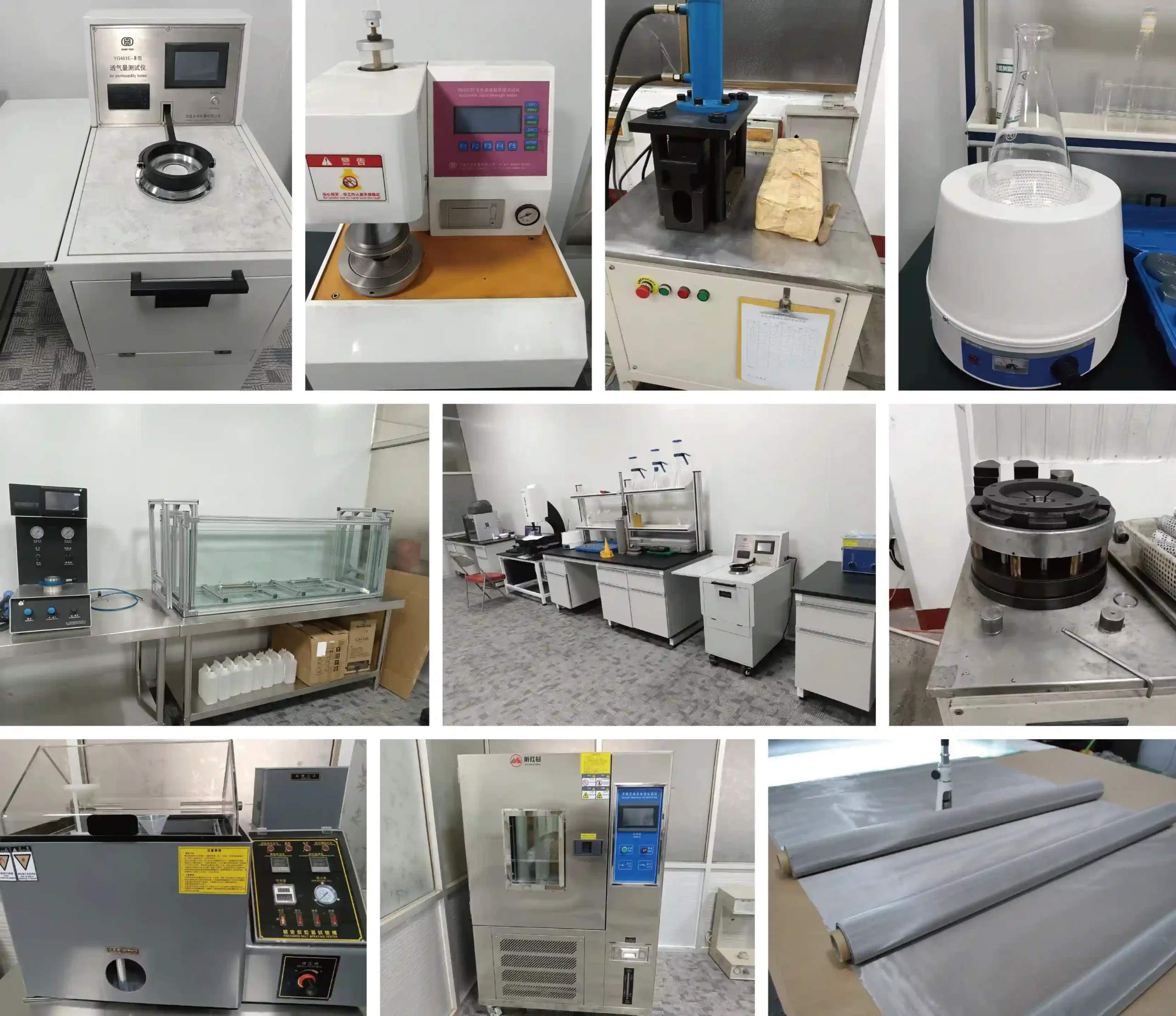
Dimensional inspection is one part of the broader filter element testing and inspection plan. Material, integrity, cleanliness and pressure-related requirements need their own appropriate evidence. A dimensional report should not claim those properties merely because fit-critical measurements passed.
Match the Review to Your Application and Product
For hydraulic filter applications, review the actual housing interface, end connection, seal and support location. A dimensionally similar replacement still needs appropriate material, retention and pressure evidence. Installation suitability cannot be inferred from length alone.
For polymer melt filtration, agree how the cold manufactured dimensions relate to the approved service design and cleaning duty. A receiving measurement does not establish thermal suitability. Surface condition, straightness and interface requirements should follow the drawing rather than improvised acceptance limits.
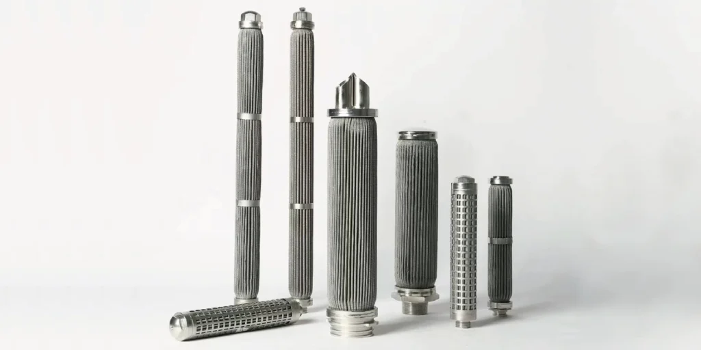
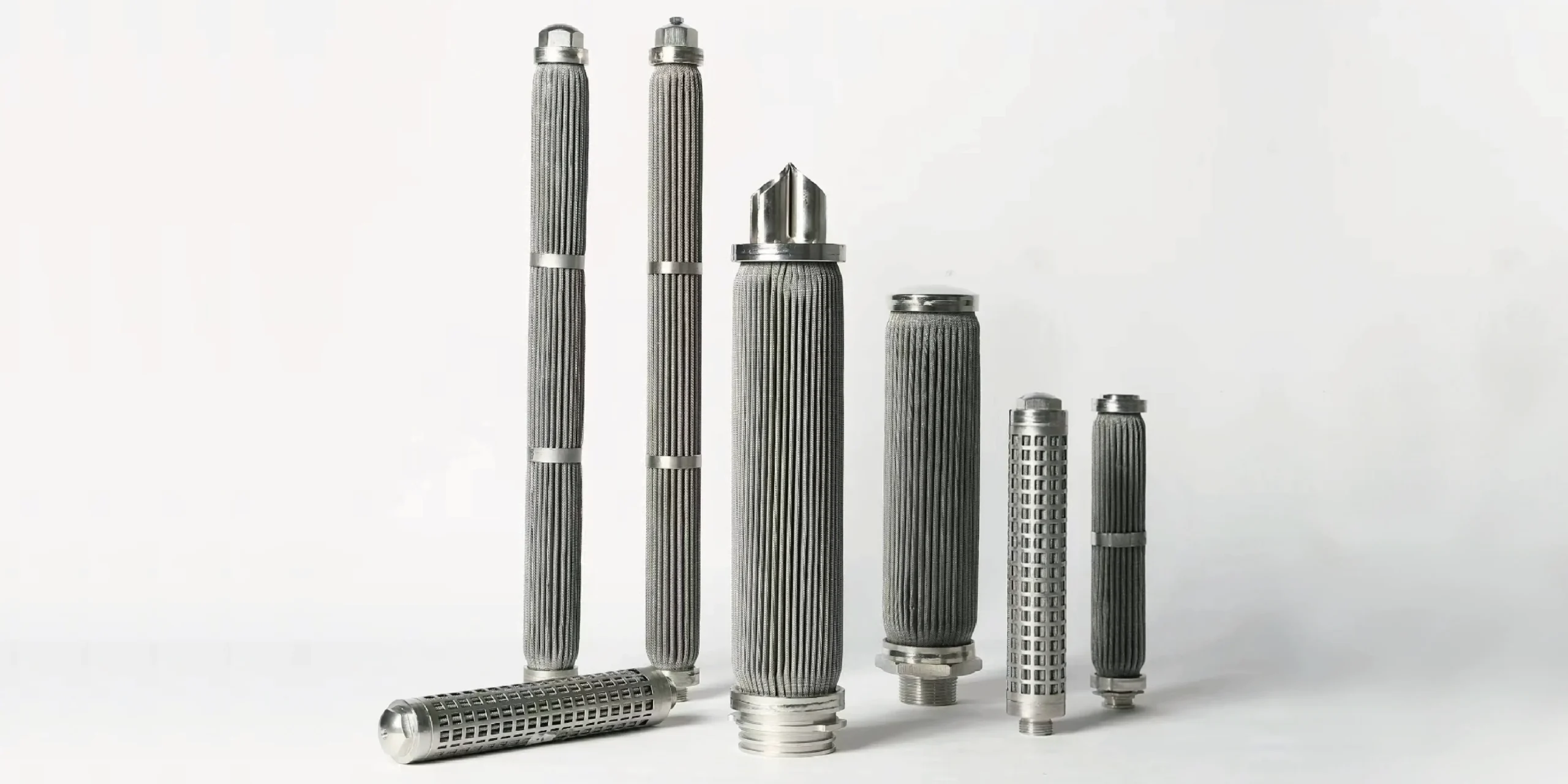
Pleated metal filter cartridges can differ in guards, end fittings and seal arrangements. Specify which finished features locate the assembly and which surface is used for each diameter measurement. Do not confuse a flexible protective feature with a rigid locating diameter.
Sintered mesh filter elements and basket filters and strainers require construction-specific checks. For baskets, rim seating and handling/removal space may be critical; for a supported cylinder, the end connection and locating dimensions may dominate. The drawing should identify those priorities explicitly.
SINFT's custom filter manufacturing service works from drawings, sample and housing information. Dimensional inspection and dimensional reports are within the confirmed product information, but the feature scope, instruments, reporting detail and any special metrology must be agreed for the order. Do not assume an unconfirmed CMM service or a standard company-wide tolerance.
What to Provide Before RFQ
Send the approved drawing, or identify that only a sample is available. Include:
- Part number, revision, units and quantity.
- Housing identification and the mating/locating features relevant to fit.
- Overall and functional dimensions, with datums and tolerances.
- Thread, flange, bayonet or other end-connection specification.
- Seal type, material, location and approved gland/interface detail.
- Sample condition, known wear or repairs, and any drawing/sample conflict.
- Required inspection coverage, actual-value report and deviation process.
- Operating fluid, temperature, pressure, flow direction and cleaning requirements for the separate design review.
An effective quotation note is:
Confirm the controlling drawing revision, functional measurement references and feature limits. State the proposed inspection coverage and report format. Identify any unresolved drawing/sample differences, and obtain written approval before changing fit-critical features or releasing a deviation.
If a replacement's fit remains uncertain, send SINFT your drawing, sample details and housing information before approving manufacture. Resolving the reference and interface questions early is more useful than receiving a long report against an ambiguous specification.
Frequently Asked Questions
Is matching overall length and diameter enough to accept a replacement?
No. The element may also depend on seating shoulders, insertion depth, end connections, seal position and locating features. An assembly can enter the housing without engaging or sealing correctly. Identify the functional dimensions on the approved drawing and inspect them using defined references. Overall size is necessary where specified, but it does not establish the complete installed fit.
Should I inspect against the old sample or the drawing?
Use the agreed controlling requirement and revision. An old sample provides useful reference information but may contain wear, deformation, repairs or a changed seal. If it conflicts with the drawing, document the differences and obtain engineering clarification. Do not silently choose whichever source makes the new part pass, or reproduce damage as though it were the original design intent.
Can a digital caliper verify every filter dimension?
No. Its suitability depends on the feature, access, tolerance, contact force and measurement arrangement. Display resolution alone does not prove accuracy or adequate uncertainty. Threads, geometric requirements and delicate surfaces may need other agreed methods. Confirm calibration status and use an appropriate inspection plan rather than treating a convenient caliper reading as complete evidence for every feature.
What if the drawing does not specify a tolerance?
Check whether a clearly applicable general tolerance or referenced specification exists. If not, ask the responsible engineer and purchaser to define the acceptance requirement. Do not invent a universal tolerance or declare compliance from the nominal value alone. Document the clarification before production or release, especially where the feature affects sealing, engagement, alignment or installation clearance.
Does a successful trial fit prove dimensional conformity?
Not by itself. It can help assess a defined installation question under an approved procedure, but may not reveal incorrect seal engagement, reduced clearance or a dimension outside the drawing limits. Preserve the dimensional record and separate functional checks. Never force an uncertain part into place or modify the housing simply to make an undocumented substitution appear acceptable.
How should seal grooves and end connections be checked?
Use the approved interface details and measurement references. Identify the thread or connector specification, engagement features, groove position and applicable dimensions or surface requirements. Record whether seals are installed during measurement. A matching outside diameter or end-code label is insufficient. Any discrepancy should receive an agreed disposition rather than an improvised seal substitution or extra tightening.
Does a dimensional inspection report prove filtration performance?
No. It records the specified geometric checks and their acceptance basis. Material identity, fabrication integrity, cleanliness, retention efficiency and pressure capability require their own relevant evidence. A part can be dimensionally acceptable while another requirement remains unresolved. Keep these checks separate within the overall inspection plan and do not expand a dimensional PASS into a general performance guarantee.
What should an actual-value dimensional report include?
Include part and sample or batch identification, drawing revision, feature references, applicable limits, units, actual readings and disposition. Record the method or instrument and relevant conditions as required by the inspection plan. Link deviations and reinspection results to the same record. This makes the document more useful than an unexplained PASS stamp or measurements without identified reference points.
Final Thoughts
Accept a replacement against a defined drawing and functional inspection plan, not just a familiar length and diameter. Agree the datums, interfaces, tolerances and decision basis, then resolve discrepancies before release. For a custom element, provide SINFT with the drawing, sample condition and housing details so manufacturing and inspection address the same requirement. Dimensional acceptance should support fit without being mistaken for proof of every performance property.