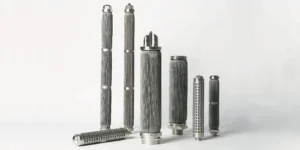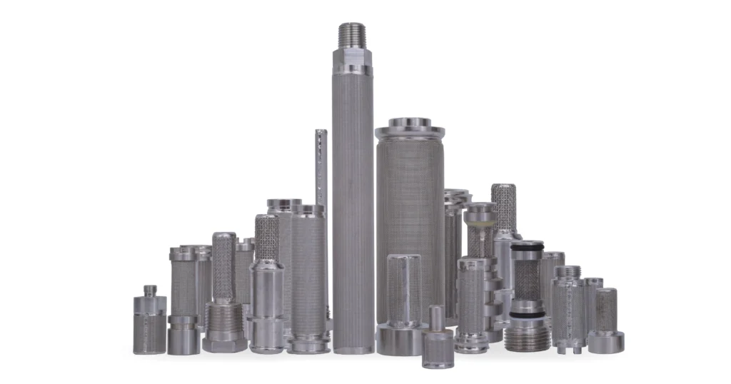
A replacement element can carry the correct part number and still have a broken wire, a widened slot or an opening at a seam. A clean appearance does not settle the question. Filter pore and slot integrity inspection helps buyers check the filtering barrier before accepting a new element or returning a cleaned one to service, using evidence appropriate to its construction.
What Should Filter Pore and Slot Integrity Inspection Establish?
The inspection should establish whether the finished filtering medium and its joints meet the agreed opening and integrity requirements. Start with the approved drawing, identify the surface or layer that controls filtration, examine accessible areas for damage, and measure openings using a suitable method. Record local irregularities as well as sampled dimensions. Where necessary, add a validated integrity test suitable for that element.
Keep three acceptance questions separate:
- Opening geometry: Do the measured apertures or slots meet the specified dimensions and tolerances?
- Barrier integrity: Is there evidence of a tear, missing wire, separated joint or other unintended flow path?
- Operating performance: Does the element meet the specified retention, pressure-drop and structural requirements under the relevant conditions?
The first two checks support an acceptance decision. They cannot establish particle-removal efficiency or all operating limits by themselves. A purchasing specification that says only “check pore size” leaves too much room for different interpretations.
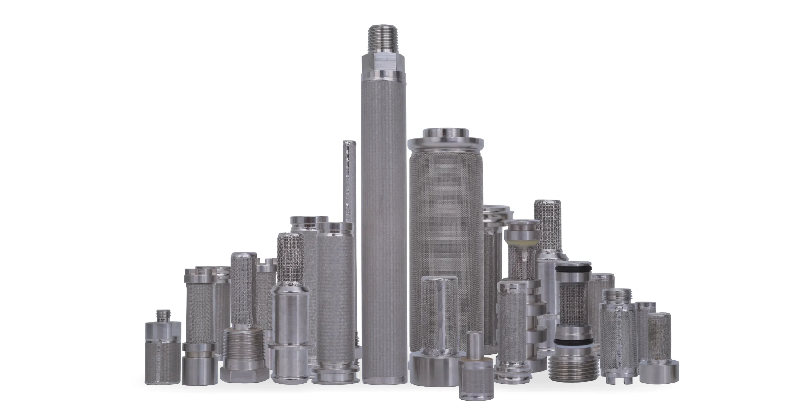
Match the Inspection Method to the Filter Construction
An opening in a single woven mesh is not the same measurement problem as a passage through a sintered multilayer structure. A continuous slot requires another approach. Before specifying equipment or a report, identify what the element actually uses to separate solids.
| Construction | Main inspection focus | Important limitation |
|---|---|---|
| Woven wire mesh | Aperture geometry, broken or displaced wires, local distortion and seam continuity | An average opening can conceal a local oversized aperture. |
| Sintered multilayer mesh | Accessible surface condition, media joints and evidence relevant to the internal control layer | The visible protective mesh may not be the layer that determines retention. |
| Sintered fiber felt or other porous depth media | Tears, crushing, separation and an agreed method for the porous structure | Irregular connected pores are not a regular grid that can be checked with a simple slot gauge. |
| Wedge wire screen | Slot width at the specified filtering surface, profile alignment and attachment condition | Measuring the wider rear opening can misrepresent the filtration slot. |
| Notch wire element | Defined gaps, profile alignment, local deformation and joint condition | The relevant measurement plane and geometry must come from the approved design. |
| Media-to-end-fitting joints | Unintended gaps, separation, damage and bypass paths around the medium | Correct media openings do not compensate for an unsealed joint. |
For a new design, resolve these distinctions before ordering. Compare the construction of sintered mesh filter elements with wedge wire filters and notch wire filter elements. Their inspection requirements should follow their actual geometry, rather than a shared label such as “stainless steel filter.”
Define the Acceptance Basis Before Measuring
The inspector needs more than a nominal micron value. Confirm the drawing revision, material and media specification, finished configuration, filtration direction and relevant surface. State whether the opening requirement concerns a nominal value, an average, a maximum local opening or a defined distribution. These are different requirements, and the report should preserve the distinction.
A usable specification identifies:
- The feature being checked and the measurement plane.
- The nominal aperture or slot width and applicable tolerance.
- Any separately defined maximum local opening or defect limit.
- The inspection method, coverage and instrument suitability.
- The treatment of seams, edges, inaccessible areas and supports.
- The required records and responsibility for releasing a nonconforming item.
Do not apply one tolerance to every mesh grade and slot design. If the order provides no acceptance limit, request clarification rather than creating a workshop limit after the element arrives. Where measurement uncertainty could affect the decision, agree how conformity will be determined. A reading displayed to several decimal places is not automatically reliable to that precision.
Also distinguish the supplied medium from the finished element. Forming, joining and handling can introduce local changes that were absent from a flat media sample. A raw-material certificate should therefore be linked to the finished part, not substituted for every finished-part check.
Start With a Documented Visual Examination
Inspect the element in a safe, accessible condition using lighting and magnification appropriate to the feature. Photograph suspicious areas before cleaning or handling changes their appearance. Packaging damage, contamination and deformation may help explain what happened; removing that evidence immediately can make the investigation harder.
Look across the accessible filtering surface, then pay particular attention to edges, end transitions, longitudinal seams, attachment points and visibly distorted areas. Check for broken or missing wires, raised edges, dents, flattened profiles, tears, separated layers and material lodged in openings. Inspect the inside where access and the agreed procedure allow it.
A shadow or dark mark is an observation, not a diagnosis. It might be trapped debris, surface discoloration or actual damage. Record its position and examine it with an appropriate method before assigning a cause. If approved cleaning is necessary, retain the initial record and inspect the same area afterward.
Avoid pushing needles, blades or improvised probes through fine openings. The inspection itself can move wires or damage the filtering layer. Passing a tool through one location does not establish the dimensions or integrity of the rest of the element.
Visual examination is valuable for locating defects and directing further checks. Its limits should remain explicit: inaccessible areas and hidden layers have not been examined simply because the outside looks uniform.
Inspect Woven Mesh Apertures Without Losing Local Defects in an Average
For woven mesh, establish the weave and the relevant directions before interpreting measurements. A square plain weave presents a different geometry from rectangular or more complex woven media. Do not assume that one face-on measurement formula applies to every metal mesh.
Haver & Boecker's wire-mesh measurement guidance describes methods for wire diameter and aperture measurement, including determining mean aperture from measured pitches and wire diameter. This is useful measurement context. It also highlights why a reported mean and the condition of an individual opening answer different questions.
For procurement inspection, ask which method was used, what was sampled and what the results represent. A mean value near the nominal specification does not resolve a separately observed opening caused by a displaced or broken wire. Evaluate that local condition against the applicable acceptance requirement.
Check areas affected by forming and joining rather than examining only an easy, undisturbed section. On curved elements, the viewing angle, surface position and access can affect what an optical image appears to show. The method must account for the geometry sufficiently to support the reported result.
Do not dismantle a finished cartridge to reproduce a raw-mesh measurement method unless a destructive examination has been specifically authorized. If the available method cannot measure the required feature on the assembled element, document that limitation and agree an alternative evidence route.
Inspect Wedge Wire and Notch Wire Slots at the Correct Surface
For a profiled-wire screen, first identify the filtering surface and the direction in which slot width is defined. A wedge-shaped profile can create an opening that widens behind the filtering surface. A convenient measurement from the rear may therefore describe the wrong part of the passage.
The Hendrick profile bar and wedge wire handbook distinguishes wire profiles and supporting structures. Use those construction distinctions when discussing the measurement plane with a supplier; do not transfer another manufacturer's slot tolerances or operating ratings to your element.
Inspect for locally widened gaps, misaligned profiles, damaged attachments and distortion near edges or welded regions. Define coverage along the relevant length and around the circumference where applicable. Measuring only one accessible slot near an open end provides limited evidence about the rest of a cylindrical screen.
Use a measurement method suited to the slot size, surface and access. If a gauge is used, its geometry and application must be appropriate and must not force the profiles apart. Optical measurements also require adequate scale, orientation and resolution. A photograph with no dependable reference scale should not become a dimensional report.
The same discipline applies to notch wire, but do not assume its gap arrangement is identical to a wedge wire screen. Confirm the actual design. For the wider selection context, see our wedge wire screen slot-size guide; nominal slot selection and finished-part integrity remain separate decisions.
Why Multilayer Sintered Mesh Needs More Than an Outer-Surface Check
A protective layer can look undamaged while the finer control layer beneath it remains unverified. Conversely, a mark on the outer guard does not by itself establish a through-defect. The assessment must relate the observation to the layer arrangement and the intended filtering path.
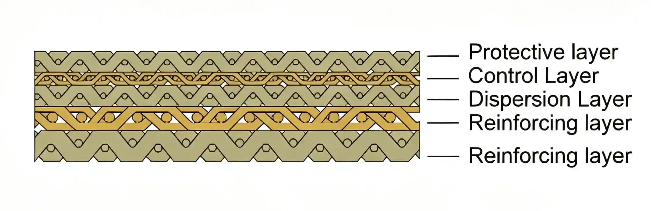
Review accessible surfaces and joints for tearing, crushing, separation and damage associated with forming or handling. Ask how the agreed inspection addresses the control layer and what remains inaccessible. Where appropriate, complementary integrity evidence may be needed for the assembled element.
Do not infer overall pore size by multiplying mesh-layer openings or by measuring only the coarsest visible layer. Avoid cutting or peeling a finished element merely to look inside unless the item is designated for an authorized destructive investigation. For production acceptance, the evidence route should be agreed before delivery.
Where Bubble-Point and Fabrication-Integrity Tests Fit
For hydraulic filter elements, the public scope of ISO 2942:2018 covers fabrication-integrity verification and determination of the first bubble point. It explicitly separates first bubble point from functional filtration characteristics: it cannot be used to estimate filtration rating, efficiency or retention capacity.
This makes test interpretation important. A suitable integrity method can provide evidence beyond a surface photograph, but its result depends on the specified procedure and conditions, including the wetting liquid. A pressure value without those conditions is not a complete acceptance record.
Confirm that the method is appropriate to the medium, assembly and purpose. Do not apply a hydraulic-element method automatically to every open-slot screen. Nor should the presence of laboratory equipment be treated as proof that a particular part passed a defined test.
Our bubble-point test guide explains the distinction in more detail. The broader filter element testing-methods guide helps keep integrity evidence separate from flow, structural and retention checks. Any pressure-based testing belongs under a suitable controlled procedure performed by qualified personnel; this article is not an operating instruction.
Turn Observations Into Clear Acceptance Actions
An inspection report should distinguish an observed condition, a suspected explanation and an approved disposition. Calling every dark opening a hole creates unnecessary rejection. Calling every irregularity cosmetic can miss a genuine bypass path.
| Observation | Question to resolve | Appropriate next action |
|---|---|---|
| Material appears lodged in an opening | Is this removable contamination or damage beneath it? | Record the initial condition; use approved cleaning if needed and reinspect. |
| One opening looks wider than surrounding openings | Is the local dimension outside the specified limit? | Measure at the correct plane and record the position and result. |
| Broken wire, tear or missing profile section | Could the condition create an unintended path? | Hold the item for technical review against the integrity criteria. |
| Outer layer looks uniform | Has the internal filtering layer been addressed? | Review construction and the agreed complementary evidence. |
| Gap appears at a seam or end transition | Is the observed gap part of the design or a joint defect? | Compare with the approved drawing and assess bypass risk. |
| A cleaned element looks brighter | Were openings, joints or supports changed by service or cleaning? | Recheck relevant features; appearance alone does not authorize reuse. |
Hold unresolved items separately from accepted stock. Any proposed repair should receive the required approval and be followed by relevant reinspection. A repair photograph alone does not close a dimensional or integrity nonconformance.
What Should the Inspection Report Contain?
Link the report to the actual delivered element or batch. A generic photograph of the same product family is useful for identification but cannot replace item-specific evidence when the order requires it.
Request the part number, drawing revision, element or batch identification, inspection date and inspection stage. Record the medium, relevant filtering surface, method and instrument identification where applicable. Include the specified limits, actual results, sampled locations and coverage. Photographs should show both the overall location and a useful close view, with scale where a dimensional interpretation is intended.
Record local defects separately from averages. State which areas could not be accessed and whether additional testing addressed those limitations. Distinguish material-stage checks from finished-element checks, and qualification evidence from routine delivery inspection.
Avoid vague conclusions such as “pore size OK” when the report does not identify what was measured. A concise report with traceable results is more useful than many photographs with no acceptance basis. The final disposition should identify accepted, held or rejected status and any authorized deviation or follow-up.
Reinspection After Service and Cleaning
Cleaning removes deposits; it does not automatically restore the original filtering geometry. Service, handling and cleaning can leave distorted profiles, damaged wires, opened joints or crushed areas. Compare the condition with the original requirements and available baseline records before returning the element to duty.
For water-treatment filtration, examine the specified slot or mesh surface and relevant joints rather than treating restored flow as proof of retention. In hydraulic filtration, maintain the distinction between integrity evidence and the performance required to protect downstream equipment.
If damage recurs in the same location, investigate operating conditions, installation, support and the approved cleaning process. Do not repeatedly repair or enlarge openings simply to reduce restriction. Changes that improve apparent flow may alter separation or structural behavior.
Specify the Evidence With the Replacement Order
Send the supplier the drawing, media construction, opening requirement, relevant tolerances, filtration direction and intended operating conditions. Identify whether the request concerns a new part, a replacement or assessment after cleaning. Include photographs and previous reports if a local defect prompted the enquiry.
SINFT lists pore/slot verification and bubble-point testing among its inspection capabilities. The applicable method, range, coverage and documentation still need confirmation for the proposed element. Do not assume that every order includes automated full-surface scanning or the same test package.
Discuss these requirements with our custom filter manufacturing team, or send your drawing and inspection requirements. Resolve the acceptance basis before manufacture so the delivered report answers the buyer's actual questions.
Frequently Asked Questions
Can visual inspection confirm a filter element's micron rating?
No. Visual inspection can identify accessible damage, irregular openings and joint problems, but it does not establish the element's particle-removal performance. Fine or hidden filtering layers may not be visible. Confirm what the stated micron rating means and request suitable performance evidence separately. Treat visual condition, opening dimensions and filtration performance as related but distinct acceptance questions.
Is average aperture enough to accept a woven mesh element?
Only if it satisfies the agreed specification and no other required criterion remains unresolved. An acceptable average does not answer a separate concern about a broken wire or locally oversized opening. Request the measurement basis, sampling locations and any applicable local limits. Evaluate visible defects independently rather than allowing a satisfactory mean to override an unresolved integrity problem.
Where should wedge wire slot width be measured?
Measure at the surface and plane defined by the approved design, normally addressing the opening that controls separation for the intended flow direction. A profiled passage can widen behind that surface, so a rear measurement may describe a different dimension. Confirm access, orientation and method with the supplier before comparing results with a stated slot-width requirement.
Can an intact outer mesh prove a sintered multilayer element is sound?
No. The outer mesh may protect or support a finer control layer that is not fully visible. Its appearance supplies only part of the evidence. Review the layer arrangement, joints and accessible damage, then confirm how the agreed inspection addresses internal integrity. Do not infer a complete acceptance result from an undamaged protective surface or a product photograph.
Does a bubble-point result prove filtration efficiency?
No. Bubble-point evidence and filtration efficiency answer different questions. A report must identify the applicable method and test conditions before its result can be interpreted. For acceptance, keep any agreed integrity requirement separate from the retention-performance requirement. A single pressure value should not replace the evidence needed to support the buyer's specified filtration efficiency or operating suitability.
Should every pore or slot be measured?
Coverage depends on the construction, feature size, accessibility and agreed acceptance plan. Do not assume a small sample means complete surface verification, or that every element can practically receive the same measurement coverage. Specify what is inspected, what is sampled and how suspect areas are investigated. The report should state limitations instead of implying unperformed full-surface inspection.
Can a cleaned element return to service if it looks clean?
Clean appearance is insufficient. Check relevant openings, joints and supports for damage or deformation and complete the acceptance checks required for that service. Use previous records where available to identify changes. If inspection leaves a suspected bypass path or structural concern unresolved, hold the element for review rather than releasing it solely because deposits have been removed.
What should buyers provide when requesting an integrity inspection?
Provide the part and drawing revision, media construction, nominal opening and tolerances, filtering surface and flow direction. State the inspection stage, required coverage and reporting needs. Include operating and cleaning conditions where relevant, plus photographs of any concern. Ask the supplier to confirm the applicable method and acceptance basis before assuming that a general inspection capability covers the requested element.
Final Thoughts
Accepting a filter element requires a clear link between its construction, the specified limits and the evidence collected. Inspect accessible surfaces, measure openings at the correct location, and address joints and hidden layers with suitable methods. Keep integrity separate from filtration performance. When a result or defect remains unresolved, clarify it before release rather than relying on a clean appearance or a nominal label.