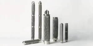
A cartridge can fit the vessel, carry the right micron label and still leave too little pressure budget for production. Choosing a longer element may help, but it does not answer whether the medium, end passage or housing is the bottleneck. Learning how to size an industrial filter cartridge means checking flow capacity and usable filtration area alongside dimensions, contaminant loading and the actual operating fluid.
Direct Answer: How to Size an Industrial Filter Cartridge
Size an industrial filter cartridge by selecting the required medium and retention level, establishing the design flow and fluid properties, then checking usable media area and clean pressure drop against the available budget. Choose a candidate length and number of parallel elements, verify loading and cleaning requirements, and confirm that the assembly fits and seals in the housing.
There is no universal flow rate per 10-inch cartridge. Two elements with the same outside dimensions can have different media, pleat geometry, supports and end passages. Use supplier data for the offered construction at the relevant conditions. This guide primarily addresses liquid service; gas and non-Newtonian polymer applications require their own condition-specific sizing data.
1. Establish the Sizing Inputs Before Choosing a Length
Start with the required separation and operating duty, not a preferred catalogue size. Record normal and maximum flow, including startup or batch peaks. Identify the fluid, temperature and viscosity at the conditions that the filter must handle.
Micron rating belongs in the same specification. A coarse medium and a finer one may have very different resistance and loading behavior. Do not solve a flow problem by relaxing the retention requirement without approval from the process owner. Use the filter micron-rating guide to clarify the required rating and its basis.
| Input | What to provide | Why it matters |
|---|---|---|
| Separation target | Particle distribution and required retention basis | Determines suitable medium and grade |
| Flow duty | Normal, peak and startup flow with units | Defines the conditions to be checked |
| Fluid properties | Viscosity and temperature together; relevant chemistry | Establishes resistance and compatibility |
| Pressure budget | Acceptable clean assembly loss and operating limits | Prevents using the whole budget on a clean filter |
| Contamination | Solids concentration, character and variability | Supports loading and maintenance review |
| Installation | Housing drawing, interfaces and removal space | Defines feasible dimensions and element count |
For hydraulic and lubricating oil filtration, cold startup can be a different sizing condition from warm operation. For polymer melt filtration, submit rheological data at the processing condition rather than a generic description such as “thick liquid.” State assumptions explicitly where measurements are not yet available.
2. Separate Envelope Dimensions from Usable Media Area
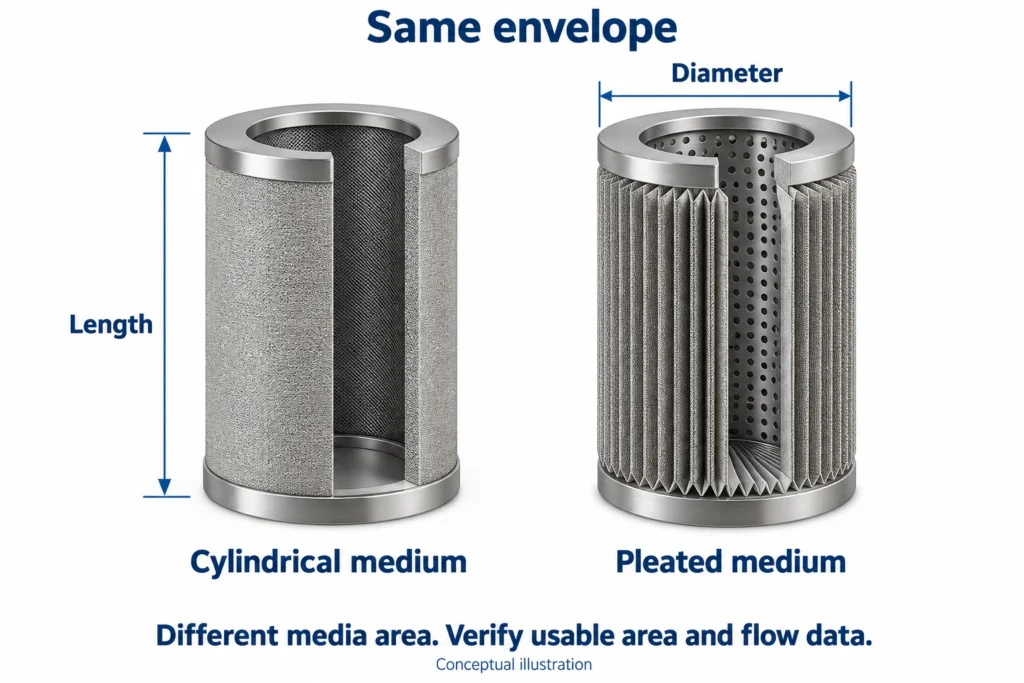
Length and outside diameter describe fit; they do not uniquely describe the available filtering surface. A plain cylindrical filtering wall and a pleated construction can occupy a similar envelope while presenting different media areas.
For an ideal, unpleated cylindrical wall, the geometric lateral area is approximately:
A = π × D × L
Here D is the diameter of the filtering surface and L is its active filtering length, not automatically the overall cartridge length. Use metres for both to obtain square metres. End caps, sealed sections and non-filtering attachments are not added to that area.
Pleated area depends on the developed filtering surface and the assembled geometry. Do not estimate it from the outside cylinder alone or assign a fixed multiplier based on appearance. Porvair's pleated cartridge catalogue illustrates the role of pleating in increasing surface area, but its product data do not establish the area or performance of a SINFT element.
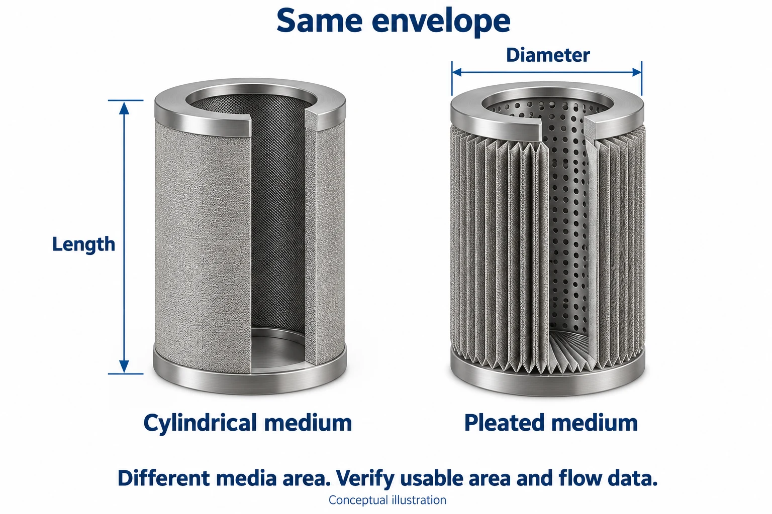
Ask the supplier how the quoted area is defined and how supports, seams and assembled flow access are accounted for. Area is useful for comparing candidates, but permeability and the complete flow path still matter. More nominal area does not by itself prove a lower assembly pressure drop.
3. Allocate the Clean Pressure-Drop Budget
Distinguish pressure loss across the elements from loss across the complete filter assembly. Housing passages, connections and cartridge hardware can consume pressure even before contamination accumulates.
Pall's liquid-sizing interface separates housing, element and assembly differential pressure. The same distinction should be explicit in a sizing enquiry, rather than comparing an element-only curve with a measurement taken across an installed vessel.
Agree on a clean assembly loss for the required flow, then establish how much of that budget remains for the elements after other losses. The allocation must also leave the system able to operate as contamination builds. Keep allowable operating differential pressure, a cleaning/replacement trigger and a destructive strength-test result separate; they are not interchangeable design inputs.
Check the pressure-tap locations, minimum downstream pressure and available supply conditions with the equipment designer. A cartridge-count calculation cannot approve a vessel, revise plant alarm settings or establish the finished element's temperature-dependent structural limit. For the wider relationship, see the filter pressure-drop and flow-rate guide.
4. Use Condition-Matched Flow Data to Screen Cartridge Count
For identical cartridges in a suitably distributing parallel housing, start with flow per element: q = Q / N. Q is total flow and N is the number of operating elements. They share the assembly's pressure difference; their individual differential pressures are not added as if they were in series.
Find the candidate element's clean pressure drop at q using supplier data for the selected medium, grade, active length and flow direction. Confirm whether the curve already includes cartridge hardware. Then combine it with separately applicable housing losses without double-counting.
If a liquid curve needs a viscosity correction, use dynamic viscosity in consistent units and the method approved for that curve. For a clean medium in a suitable linear-flow regime, a screening relationship may be written:
ΔP₂ ≈ ΔP₁ × (q₂ / q₁) × (μ₂ / μ₁)
This approximation keeps the cartridge geometry and medium unchanged. It is not a universal rule for loaded media, compressible gas, non-Newtonian melt or significant nonlinear passage losses. Pall's Principles of Filtration, particularly its flow, viscosity and pressure-drop discussion, explains why the fluid conditions and available pressure belong together in filter selection.
If viscosity is supplied in cSt, it is kinematic viscosity, not the cP quantity in the equation. Convert using density at the same temperature: μ (cP) = ν (cSt) × density (g/cm³). Do not substitute a cSt number directly for a cP number.
Worked Example: A Hypothetical Hydraulic Screening Calculation
The following values are invented teaching inputs, not SINFT test results, recommended operating limits or a real customer case. Assume identical parallel cartridges, equal flow sharing and an element curve that permits linear flow/viscosity scaling in the range being evaluated.
| Assumed input | Value |
|---|---|
| Required total flow | 120 L/min |
| Process liquid dynamic viscosity | 4 cP at the sizing temperature |
| Reference element-only loss | 0.05 bar at 20 L/min and 1 cP |
| Chosen clean assembly-loss budget | 0.30 bar at total flow |
| Assumed housing loss at total flow | 0.05 bar, separately established |
| Remaining clean element-loss budget | 0.25 bar |
For N identical elements:
q = 120 / N L/min
ΔP element ≈ 0.05 × [(120 / N) / 20] × (4 / 1) = 1.20 / N bar
The clean element screen requires 1.20 / N ≤ 0.25, so N ≥ 4.8. Round up to five operating elements for this hypothetical check.
- Four elements: q = 30 L/min each; element loss ≈ 0.30 bar; assembly loss ≈ 0.35 bar. This exceeds the assumed clean budget.
- Five elements: q = 24 L/min each; element loss ≈ 0.24 bar; assembly loss ≈ 0.29 bar. This passes the assumed clean hydraulic screen.
Five is not a final specification. The assumed reference data and housing loss must be valid for the offered construction and actual fluid. Contaminant loading, maintenance interval, temperature extremes, retention, mounting and structural limits remain unresolved. If the available housing has only four positions, the answer is to reassess feasible construction or system design—not to round 4.8 down.
5. Compare Longer Elements with More Parallel Elements
Longer elements and more parallel elements are different installation options, not automatically equivalent hydraulic solutions. Compare them using actual usable area, flow data and housing geometry.
For candidates with the same medium, grade and construction, adding active length may increase area. However, the core, end connection and collection passages can affect the result. Doubling the nominal length does not guarantee halving the complete assembly loss.
More parallel elements reduce the average flow per element only when the housing distributes flow appropriately. The additional positions also need space, suitable seating and maintenance access. Closely packed elements or a restricted outlet can leave a housing bottleneck even when the media area looks adequate.
Where the supplier provides an accepted superficial flux for the particular duty, A required = Q / J and N area = round up(A required / A usable per element) can serve as an area screen. Keep flow and flux units consistent. Do not invent a universal allowable flux, and do not treat this calculation as a substitute for the pressure-drop and loading checks.
6. Check Loading, Cleaning and the Maintenance Interval
A low clean pressure drop does not establish how long the filter will run. The type and quantity of contamination, its interaction with the medium and the available operating headroom determine whether the hydraulic candidate is practical.
Request the solids concentration and particle distribution where available. For an idealized liquid mass-loading estimate, incoming solids rate is Q × C, using compatible volume/time and mass/volume units. That is incoming mass, not automatically captured mass or validated dirt capacity. Retention and contaminant behavior must also be established.
Select the medium for the intended capture and cleaning behavior. Sintered mesh elements and sintered fiber felt filters provide different filtering constructions; their service life cannot be compared from equal length or area alone.
Define whether the maintenance target is a batch, shift or another operating interval. Ask what evidence supports the proposed capacity and cleaning method. If representative loading data are unavailable, identify a qualification trial rather than claiming a lifetime. Backwashing capability also needs an approved reverse-flow duty; extra media area does not establish that approval.
7. Verify Housing Fit, Sealing and Removal Space
A hydraulically suitable cartridge must still seat, seal and be removable in the intended housing. For replacement work, record the overall and active lengths separately, along with OD, bore, connection and seal location.
Do not assume that two nominal “10-inch” elements have identical installed dimensions. Check the seating datum, insertion depth, end-cap arrangement, retaining hardware and seal groove against the drawing or sample. Confirm the flow direction and supporting structure for the stated forward and reverse loads.
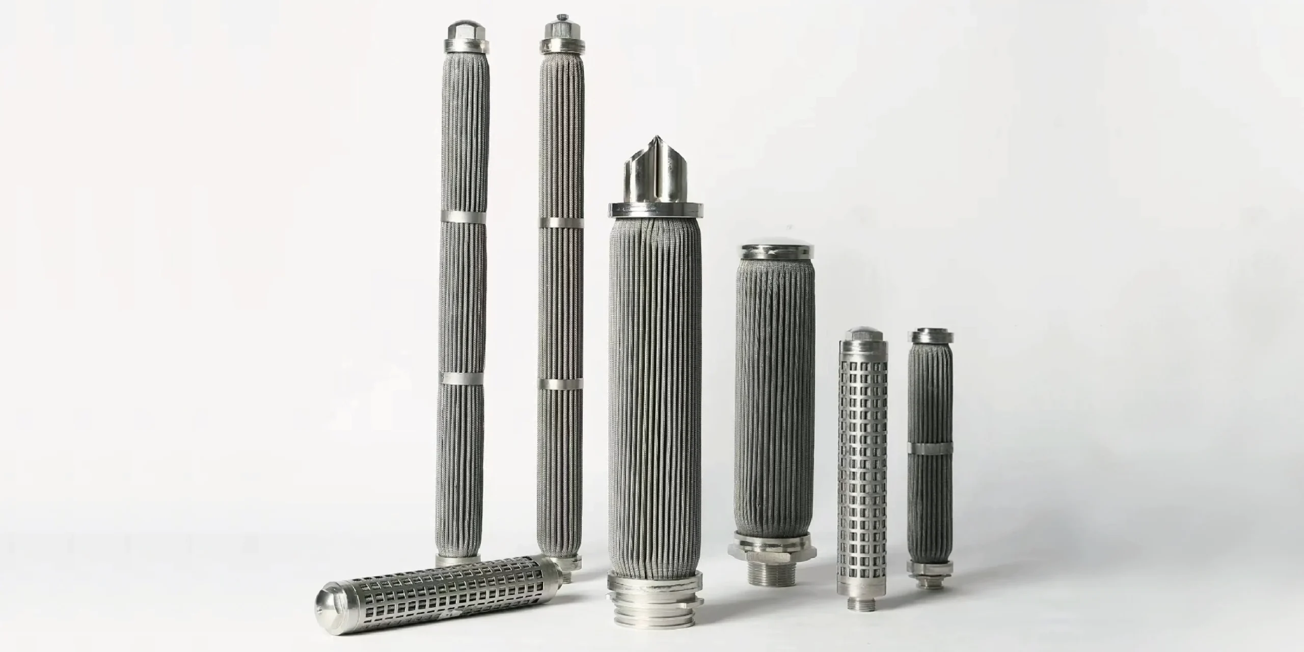
Review element-to-element spacing, bore/collection passages and installation orientation with the housing designer. Include lid opening and the space needed to withdraw the element safely. A longer cartridge that cannot be removed in the plant is not a workable sizing choice, even if it meets the calculated clean-flow requirement.
What to Send Before RFQ
Give the supplier enough information to connect the sizing calculation with the actual assembly. Include:
- Fluid identity, composition and viscosity/density at normal and startup temperatures.
- Total flow, peak duty, units and number of simultaneously operating elements.
- Retention target, rating basis, contamination type and loading information.
- Clean assembly pressure-loss budget, measurement locations and operating differential limits.
- Proposed medium and material, or a request to review the selection.
- Housing drawing, element positions, OD/ID, lengths, seating datum and interfaces.
- Seal specification, flow direction, cleaning conditions and maintenance target.
- Existing part number, sample or photos for replacement matching.
- Quantity and required dimensional, material or inspection documentation.
Request the condition-matched flow data and the assumptions behind the recommended length/count. Make unresolved loading or fit requirements visible before approving manufacture.
How SINFT Can Help
SINFT can review drawings, samples, housing dimensions and process conditions for custom metal cartridges and replacement elements. A useful enquiry combines the duty data with the installation drawing rather than asking for a universal flow-rated size.
Pleated filter cartridges are relevant when filtering area must be accommodated within a limited envelope. Sintered mesh and fiber felt provide alternative constructions according to retention, loading and cleaning requirements. SINFT can review lengths, diameters, interfaces, materials and supporting parts against the specified duty; final ratings require confirmation for the offered assembly.
Use the custom filter manufacturing service for non-standard dimensions or old-sample matching. Submit the flow conditions and housing drawing so the enquiry can address both hydraulic suitability and physical fit. This does not replace the equipment designer's approval of the housing or overall process.
Frequently Asked Questions
What flow rate can a 10-inch industrial cartridge handle?
There is no single flow rate for all 10-inch cartridges. Medium, retention grade, usable area, connections, liquid viscosity and acceptable pressure loss determine the relevant capacity. Ask for a curve or sizing basis for the exact offered construction and operating conditions. A nominal length or generic maximum-flow statement is not enough to compare candidates or establish a maintenance interval.
How do I calculate the number of cartridges required?
Start with total flow divided by the number of identical parallel operating elements, then check the resulting per-element flow against condition-matched data. Include housing losses, loading allowance and installation constraints. Round a calculated minimum up, not down. The hydraulic count remains provisional until the element, housing flow distribution, retention and maintenance duty have all been reviewed for the intended application.
Does twice the cartridge length mean twice the flow capacity?
Not automatically. Added active length can increase media area for a comparable construction, but internal passages, end connections and housing losses may prevent proportional improvement. Nominal length also includes parts that do not filter. Compare the supplier's usable area and performance data for both lengths at the same conditions, then check whether the longer element can be installed and removed.
Can I size a cartridge using only outside diameter and length?
Those dimensions establish an envelope, not a complete hydraulic specification. Pleating, media grade, thickness, support contact and internal passages change resistance and usable surface. Start with the required separation and fluid duty, then use construction-specific flow data to assess candidate dimensions and count. Finally verify the sealing interface, mounting and maintenance clearance against the actual housing drawing or replacement sample.
Should I use normal or startup viscosity for sizing?
Check both whenever they represent materially different operating conditions. A cold liquid startup may require a separate flow/pressure assessment from stabilized operation. Pair viscosity with the temperature and requested flow for that state; do not apply one viscosity value to the entire duty. Use the approved plant startup basis and obtain supplier confirmation before assuming that the normal-service sizing also covers startup.
Will a low clean pressure drop guarantee a long service life?
No. Clean loss describes initial hydraulic resistance, not validated contaminant capacity. Particle load, retention, deposit behavior, cleaning effectiveness and the allowable operating headroom govern the service interval. Where representative loading information is missing, identify the need for qualification rather than promising life from area alone. A candidate that passes the clean-flow screen still needs a loading and maintenance review.
Final Thoughts
Size the cartridge for its filtering duty and installed assembly, not just its envelope. Begin with retention, flow and fluid properties; compare usable area and condition-matched pressure-drop data; then check loading, limits and fit. A rounded-up hydraulic minimum is only a candidate. Sending a clear duty sheet and housing drawing helps turn that candidate into a specification that can be reviewed before manufacture and installation.