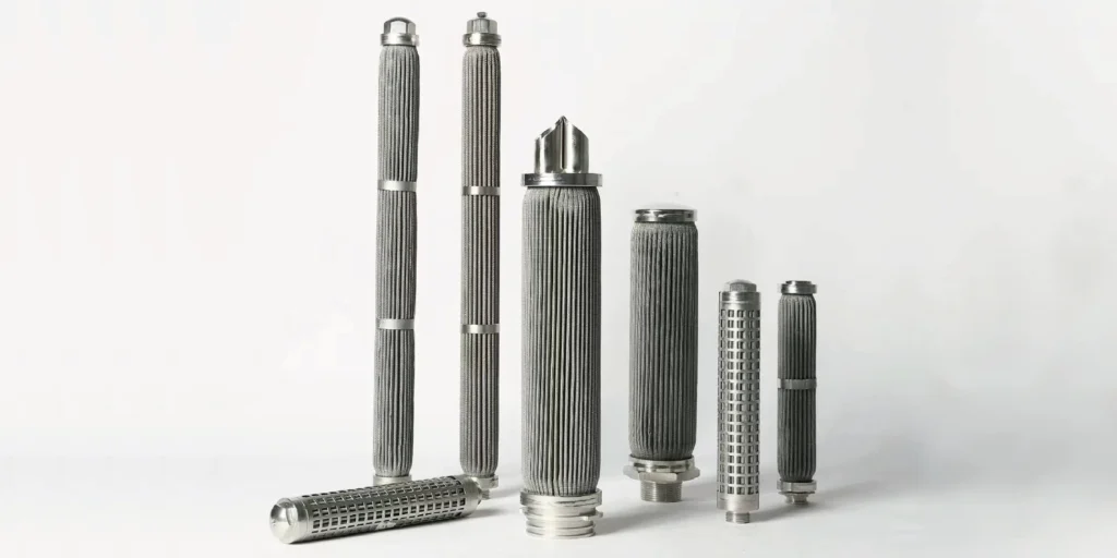
When a filter looks correct on paper but starves a pump, opens bypass during cold start, or reaches its cleaning alarm too quickly, the missing check is often pressure drop at the real flow condition. Filter pressure drop vs flow rate is not a catalog footnote; it decides whether the selected element can work in your actual system.
Direct Answer: Filter Pressure Drop vs Flow Rate
As flow rate increases through a filter, differential pressure normally rises. The exact curve depends on the filter medium, effective area, pore or slot structure, element geometry, housing, fluid viscosity and density, temperature, and contaminant loading. For selection, use the manufacturer’s curve for the correct element and housing, then compare clean and terminal pressure drop under your real operating conditions.
What Is Filter Pressure Drop?
Filter pressure drop is the pressure difference between the upstream and downstream sides of a filter while fluid is flowing. It is commonly written as ΔP, dP, DP, or differential pressure:
ΔP = upstream pressure − downstream pressure
Pressure drop is not the same as operating pressure. A housing can operate at a high line pressure while the pressure difference across a clean element remains relatively small. The element’s structural differential-pressure capability and the complete housing’s pressure rating are also different specifications and must not be interchanged.
For a complete filter assembly:
Total clean ΔP = housing loss + element loss + losses through valves or other in-flow components
That separation matters when comparing suppliers. One curve may show only the clean element, while another shows the element and housing together.
Filter Pressure Drop vs Flow Rate: What Changes the Curve?
Higher flow normally creates higher pressure drop, but the shape and slope of the curve are product- and fluid-specific. The following factors control the result.
| Variable | Typical effect when it increases | Why it matters |
|---|---|---|
| Flow rate | Pressure drop increases | More fluid must pass through the same flow area |
| Fluid viscosity | Pressure drop increases | A more viscous fluid resists movement through the medium |
| Fluid density | Can increase housing and flow-path losses | Density affects inertial losses and correction methods |
| Effective filter area | Pressure drop decreases at the same total flow | More area lowers flow per unit area |
| Media resistance or fineness | Pressure drop often increases | Smaller or more tortuous flow paths add resistance |
| Contaminant loading | Pressure drop increases | Deposited solids reduce available flow paths |
| Temperature of a liquid | Pressure drop often falls as temperature rises | Many liquids become less viscous when warmer |
| Number of elements in parallel | Pressure drop per element decreases | Total flow is divided among more elements |
These are directional relationships, not universal correction factors. Use the actual manufacturer’s curve and sizing method whenever available.
For clean flow through a porous medium, Darcy’s law provides a useful conceptual model:
Q = kAΔP / μL
where Q is volumetric flow, k is permeability, A is effective area, ΔP is differential pressure, μ is dynamic viscosity, and L is the effective flow-path thickness. Real industrial filters can depart from this simplified relationship because the housing, supports, pleats, slots, transitions, turbulence, compressibility, and contaminant cake also contribute resistance.
What Standard Applies to Pressure Drop vs Flow Testing?
ISO 3968:2017 is the current international standard for evaluating differential pressure versus flow characteristics of hydraulic filters. It specifies measurement at different flow rates and viscosities for relevant parts of the assembly, including the filter element, housing, spin-on unit, and valves in the flow stream.
The standard creates a basis for agreement between manufacturer and user; it does not turn one tested curve into a universal curve for all fluids or filter designs. A curve produced for hydraulic oil under controlled conditions should not be applied directly to water, compressed gas, steam, or polymer melt.
ISO 3968:2017 should therefore be treated as a defined test framework for its stated scope. For process filters outside that scope, the buyer should still request equivalent clarity about test fluid, viscosity, density, temperature, element size, housing, flow direction, and whether the element was clean or loaded.
How to Read a Filter Pressure-Drop-versus-Flow Curve
Read the curve only after confirming what was tested and under which conditions. Use this sequence.
1. Confirm the curve identity
Check the exact filter model, element length, media grade, micron rating, housing size, port size, seal configuration, and flow direction. A curve for a 20-inch element cannot be assumed to represent a 10-inch element.
2. Check the test conditions
Record:
- Test fluid
- Viscosity and density
- Fluid temperature
- Inlet pressure for gas service
- Clean or loaded element condition
- Whether the curve includes the housing
- Actual or standard volumetric flow units
3. Locate the design flow
Use the maximum normal operating flow, not only the average. Also evaluate start-up, upset, peak demand, and any reverse-flow or cleaning condition relevant to the design.
4. Read the clean differential pressure
Move from the flow-rate axis to the correct media curve, then read the corresponding ΔP. Keep the units consistent; do not mix psi, psid, bar, kPa, gpm, L/min, actual cubic flow, and standard cubic flow.
5. Apply only an approved correction
Correct for actual viscosity, density, and temperature using the manufacturer’s stated method. Do not assume a water curve can be scaled to oil with a single generic multiplier.
6. Add the complete assembly losses
If the element and housing are shown separately, add both. Include any bypass valve, check valve, manifold, or connection loss required by the supplier’s method.
7. Compare with the design limits
Check the calculated clean ΔP against:
- Available system pressure budget
- Pump or blower operating point
- Bypass-valve setting, if present
- Differential-pressure indicator range
- Terminal cleaning or replacement criterion
- Element differential-pressure capability
- Housing and system design requirements
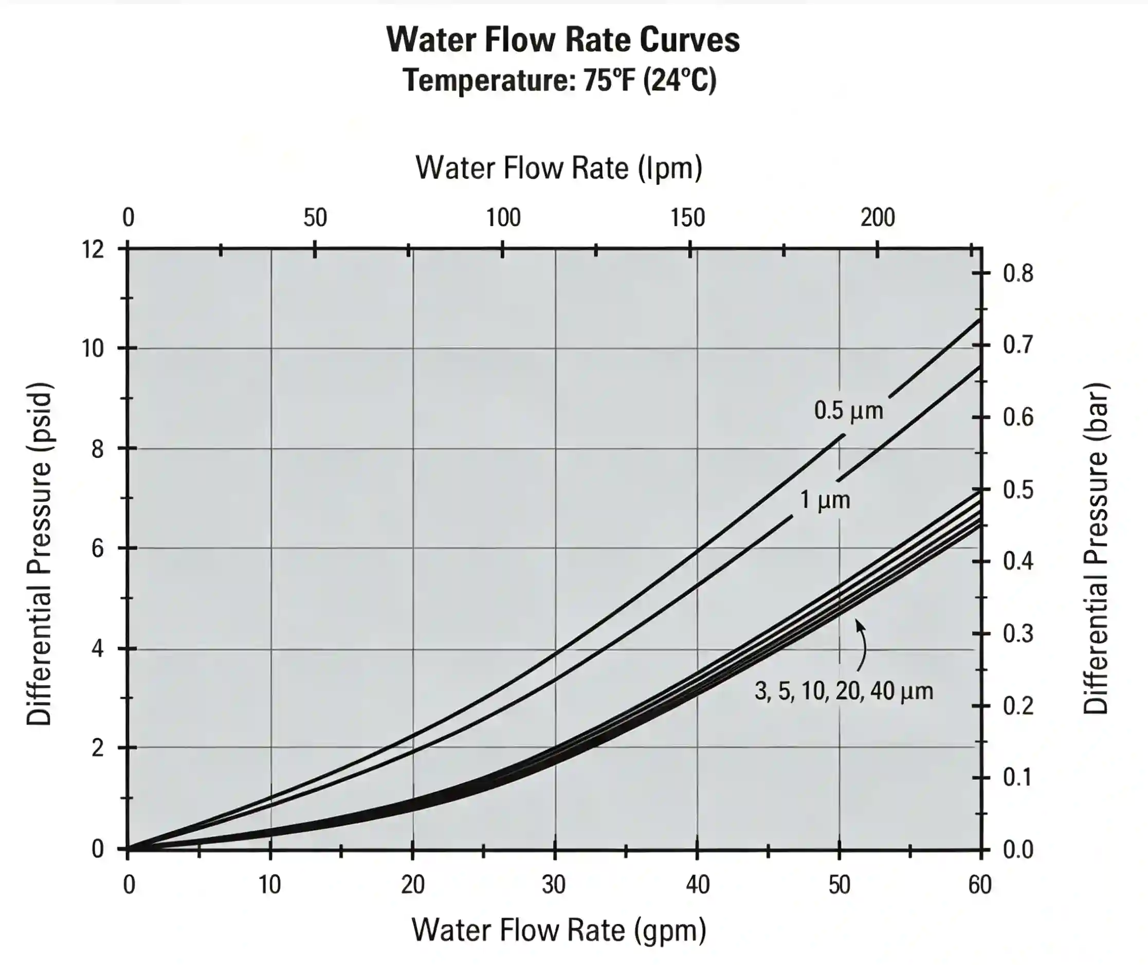
The example illustrates two important points: pressure drop rises with water flow, and media grades can follow different curves. It should only be used for the filter construction and reference conditions represented by the chart.
Why Viscosity and Temperature Matter
For liquid filtration, viscosity is often the most important correction between a published curve and the real process. A cold oil can create far more resistance than the same oil at normal operating temperature.
Donaldson’s hydraulic filtration guidance states that higher viscosity creates higher pressure drop and that the lowest potential fluid temperature should be considered when evaluating cold-start conditions. Its sizing examples identify flow rate, viscosity, fluid type, and filtration grade as required inputs.
Evaluate at least two conditions:
- Normal operation at stabilized temperature.
- Start-up or minimum-temperature operation at the highest expected viscosity.
If cold-start ΔP is excessive, the filter may enter bypass, restrict pump inlet conditions, or fail to deliver the required flow even though the warm operating point looks acceptable.
Possible design responses include increasing the element area, selecting a larger housing, adding elements in parallel, reducing flow per element, or reviewing a more permeable medium that still meets the required retention efficiency. Temperature should only be changed when the process and material compatibility permit it.
Why Gas and Liquid Curves Are Not Interchangeable
Gas-flow calculations require the stated inlet pressure, temperature, and flow basis because gas is compressible. A water-flow curve does not describe air performance, and a standard-liter-per-minute value is not the same as actual volumetric flow at every pressure.
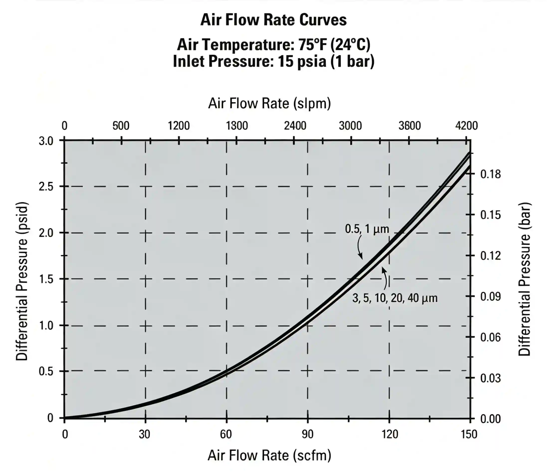
When requesting a gas-filter review, provide:
- Gas composition
- Actual inlet pressure and temperature
- Normal and maximum flow
- Whether flow is stated as actual or standard volume
- Allowable clean and terminal ΔP
- Required particle retention
- Condensation or liquid carryover risk
The same caution applies to steam and high-temperature gas. Seal limits, thermal expansion, flow direction, and material compatibility must be checked separately from the pressure-drop curve.
Clean Filter vs Loaded Filter Pressure Drop
Clean ΔP is the baseline resistance of a new or properly cleaned element; loaded ΔP includes the additional resistance from retained contamination. At constant flow, ΔP usually rises as particles block pores or form a cake. In a system that cannot maintain flow, the flow rate may decline instead.
Trend differential pressure only under comparable conditions. A higher reading can result from:
- More contaminant loading
- Higher flow
- Lower liquid temperature
- Higher viscosity
- A valve-position change
- A different pump operating point
- A blocked downstream line
- An incorrect or damaged pressure instrument
For this reason, a single ΔP alarm should not automatically be interpreted as a measured mass of dirt. Compare the reading with flow and temperature, then follow the approved equipment limit.
There is no universal industrial rule such as “clean at exactly x bar” or “replace at exactly twice the clean pressure drop.” The terminal value must come from the filter and housing design, bypass setting, process requirement, and approved operating procedure.
For automatic systems, differential pressure can be used as a backwash trigger, but the set point must leave enough operating margin. SINFT manufactures backwash filter cartridges using stainless steel mesh, reinforced basket, or slot structures for reverse-flow, air-blow, and automated cleaning arrangements.
How Filter Construction Changes Pressure Drop
Media area and flow-path geometry often matter as much as the nominal micron rating. Two elements with the same rating may have different clean ΔP and loading behavior.
| SINFT construction | Relevant design characteristic | What the buyer should confirm |
|---|---|---|
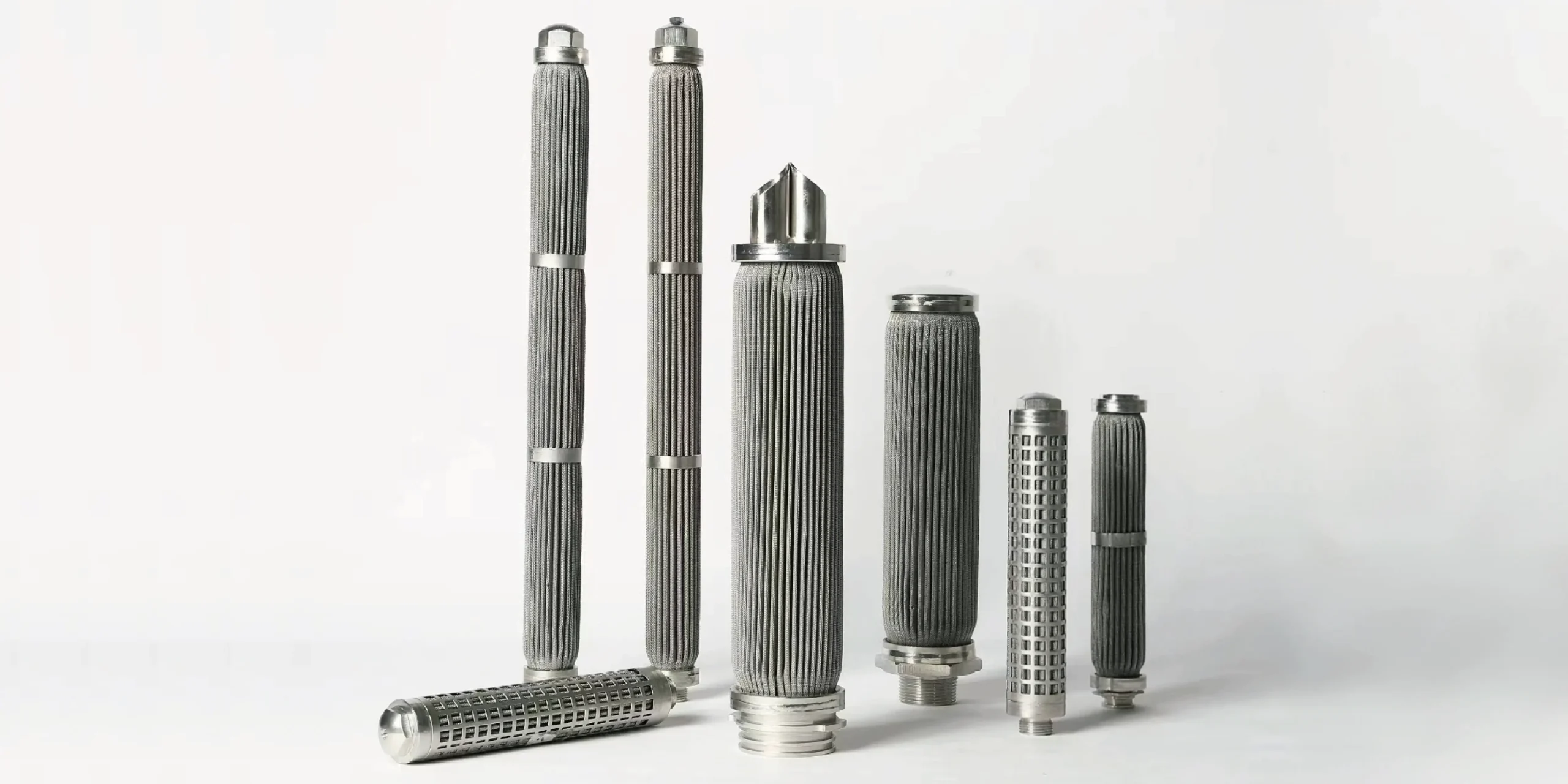
| Pleated filter cartridge | Pleats increase effective area within the housing envelope | Media grade, pleat geometry, area, flow direction, and clean curve |
| Sintered mesh element | Rigid multi-layer structure provides stable pores and mechanical support | Layer structure, permeability, thickness, size, and cleaning direction |
| Sintered fiber felt | Three-dimensional depth medium with high porosity and dirt capacity | Grade, support mesh, efficiency, loading curve, and cleaning method |
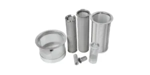
| Basket or tube element | Perforation, woven mesh, or sintered liner provides coarse or intermediate protection | Open area, mesh or aperture, basket area, housing clearance, and debris load |
| Wedge wire element | Continuous V-shaped slots can provide high open area and surface cleanability | Slot width, profile geometry, open area, flow direction, and backwash method |
SINFT’s pleated filter cartridges can use woven wire mesh, sintered wire mesh, or sintered metal fiber felt. The website lists 0.5–200 µm depending on medium, but that filtration range does not define a single pressure-drop curve. Each selected construction still needs a condition-specific hydraulic or gas review.
How to Reduce Excessive Filter Pressure Drop
Reduce excessive ΔP by lowering flow per unit area, correcting the filter size, or restoring available flow paths—without sacrificing the required retention performance.
Practical options include:
- Increase element length or effective filtration area.
- Use a larger housing or lower-loss connection.
- Install multiple elements or housings in parallel.
- Add coarse pre-filtration when large debris prematurely loads the final element.
- Review media permeability and micron efficiency together.
- Clean, backwash, or replace the element at the approved terminal ΔP.
- Reduce avoidable fittings, restrictions, or undersized ports.
- Check cold-start viscosity and minimum process temperature.
- Verify that the element is installed in the intended flow direction.
- Confirm that the differential-pressure instrument and impulse lines are working correctly.
For pipeline strainers, a larger free straining area can reduce clean resistance and increase dirt capacity. The basket strainer vs Y strainer comparison explains how housing geometry, debris load, installation space, and cleaning access affect that decision.
Filter Sizing Checklist
Before approving a filter, confirm:
- Required normal and maximum flow
- Fluid or gas identity
- Density and viscosity at normal and minimum temperature
- Operating and design pressure
- Allowable clean and terminal ΔP
- Element, housing, and complete-assembly curves
- Particle size, concentration, and loading variability
- Required micron efficiency or slot opening
- Effective area and number of elements
- Bypass or relief arrangement
- Flow direction
- Cleaning, backwash, or replacement method
- Start-up and upset conditions
- Connection size and housing geometry
- Required material and seal compatibility
For hydraulic systems, see SINFT’s hydraulic and lubrication filtration guide for available pleated, sintered mesh, fiber felt, backwash, and wedge-wire constructions.
What Buyers Should Confirm Before RFQ
Send the following information for an application-specific pressure-drop review:
- Working liquid, gas, steam, or polymer.
- Normal, minimum, and maximum flow rate.
- Flow units and whether gas flow is actual or standard.
- Operating and design pressure.
- Inlet pressure for gas service.
- Normal and minimum operating temperature.
- Viscosity and density at the stated temperatures.
- Allowable clean and terminal differential pressure.
- Contaminant type, concentration, and particle-size distribution.
- Required micron efficiency, aperture, or slot width.
- Element OD, ID, length, connection, seal, and flow direction.
- Existing housing, drawing, old sample, photo, or part number.
- Cleaning method and required operating cycle.
- Required material certificates and inspection records.
SINFT can review these inputs through its custom filter manufacturing service and match an element to a drawing, old sample, housing dimensions, or specified connection.
How SINFT Can Help With Pressure-Drop-Based Filter Selection
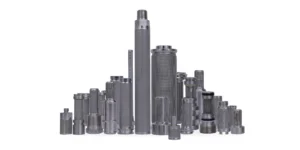
SINFT can help when the pressure-drop question is tied to a real element geometry, media choice, or replacement problem. Depending on the duty, the review may involve pleated filter cartridges, sintered mesh filter elements, sintered fiber felt filters, basket filters and strainers, or backwash filter cartridges.
If you are replacing an existing element, send the old element dimensions, end connection, seal position, flow direction, media type, and current pressure-drop behavior. If you are designing a new process or OEM system, send the flow range, fluid or gas properties, viscosity, temperature, contaminant load, required retention, allowable clean and terminal differential pressure, and cleaning method. SINFT can then review whether the issue is media area, micron selection, housing fit, cold-start viscosity, contaminant loading, or element construction.
Frequently Asked Questions
Does filter pressure drop increase with flow rate?
Yes, under otherwise comparable conditions. The exact relationship depends on media permeability, effective area, housing geometry, viscosity, density, temperature, and whether the element is clean or loaded. If your system operates across a wide flow range, check the maximum normal flow and any start-up or upset condition instead of sizing only around the average flow.
How do you calculate pressure drop across a filter?
Use the manufacturer’s pressure-drop-versus-flow curve for the exact element and housing, correct it for the actual fluid using the approved method, and add the element, housing, valve, and manifold losses included in the system. Do not mix a clean-element curve from one supplier with a complete-housing curve from another unless the tested boundaries are clear.
Why is filter pressure drop high during cold start?
Many liquids become more viscous at low temperature. The more viscous fluid encounters greater resistance through the media, so cold-start pressure drop can be much higher than warm operating pressure drop. If you ignore the lowest operating temperature, the filter may enter bypass, restrict pump suction, or trigger an alarm even when the warm curve looks acceptable.
Does a finer micron rating always cause higher pressure drop?
Not always. Finer media often add resistance, but effective area, pleat design, porosity, thickness, support layers, and housing geometry also matter. A larger pleated element with finer media may have lower clean pressure drop than a smaller element with coarser media. Compare products under the same flow, fluid, temperature, and clean or loaded condition.
When should a filter be cleaned or replaced?
Use the terminal differential pressure approved for the element, housing, bypass arrangement, and process. Confirm the reading at a known flow and temperature before treating it as a loading alarm. A pressure rise may indicate contaminant loading, but it can also come from higher flow, colder fluid, valve changes, blocked downstream piping, or instrument problems.
What pressure-drop data should I send for a custom filter quote?
Send normal and maximum flow, fluid or gas type, viscosity, density, operating temperature, minimum start-up temperature, clean pressure-drop target, terminal differential-pressure limit, contaminant load, required retention, element dimensions, housing data, flow direction, and cleaning method. If you already have pressure-drop readings from the field, include the flow and temperature recorded at the same time.
Final Thoughts
Filter pressure drop vs flow rate is where filtration theory becomes a purchasing decision. A filter that is too small, too fine, poorly matched to viscosity, or wrong for the loading pattern can cost more in alarms, bypass events, cleaning labor, and short service life than in element price. SINFT can review your flow condition and element data before recommending a custom filter construction.
Request a Filter Sizing Review
A pressure-drop curve becomes useful only when it is matched to the actual flow, viscosity, temperature, element geometry, housing, and loading condition. Send SINFT your process data, drawing, old element, or housing dimensions for an engineering review.
Request a custom filtration quote
Technical References
- ISO, “ISO 3968:2017 — Hydraulic fluid power — Filters — Evaluation of differential pressure versus flow”: https://www.iso.org/standard/64104.html
- Donaldson, “Hydraulic Filtration Overview”: https://www.donaldson.com/content/dam/donaldson/engine-hydraulics-bulk/literature/emea/hydraulic/f116091/eng/Hydraulic-Filtration-Overview.pdf
- Eaton, “Manual Pipeline Strainers Technical Support Guide”: https://www.eaton.com/content/dam/eaton/products/filtration-solutions/filter-systems-and-strainers/filters-and-strainers/manual-pipeline-strainers/brochures/Eaton-Manual-Pipeline-Strainer-Technical-Support-Guide-EN-LowRes.pdf
- Parker Hannifin, “The Handbook of Hydraulic Filtration”: https://www.parker.com/content/dam/Parker-com/Literature/Hydraulic-Filter-Division-Europe/fdhb289uk.pdf