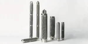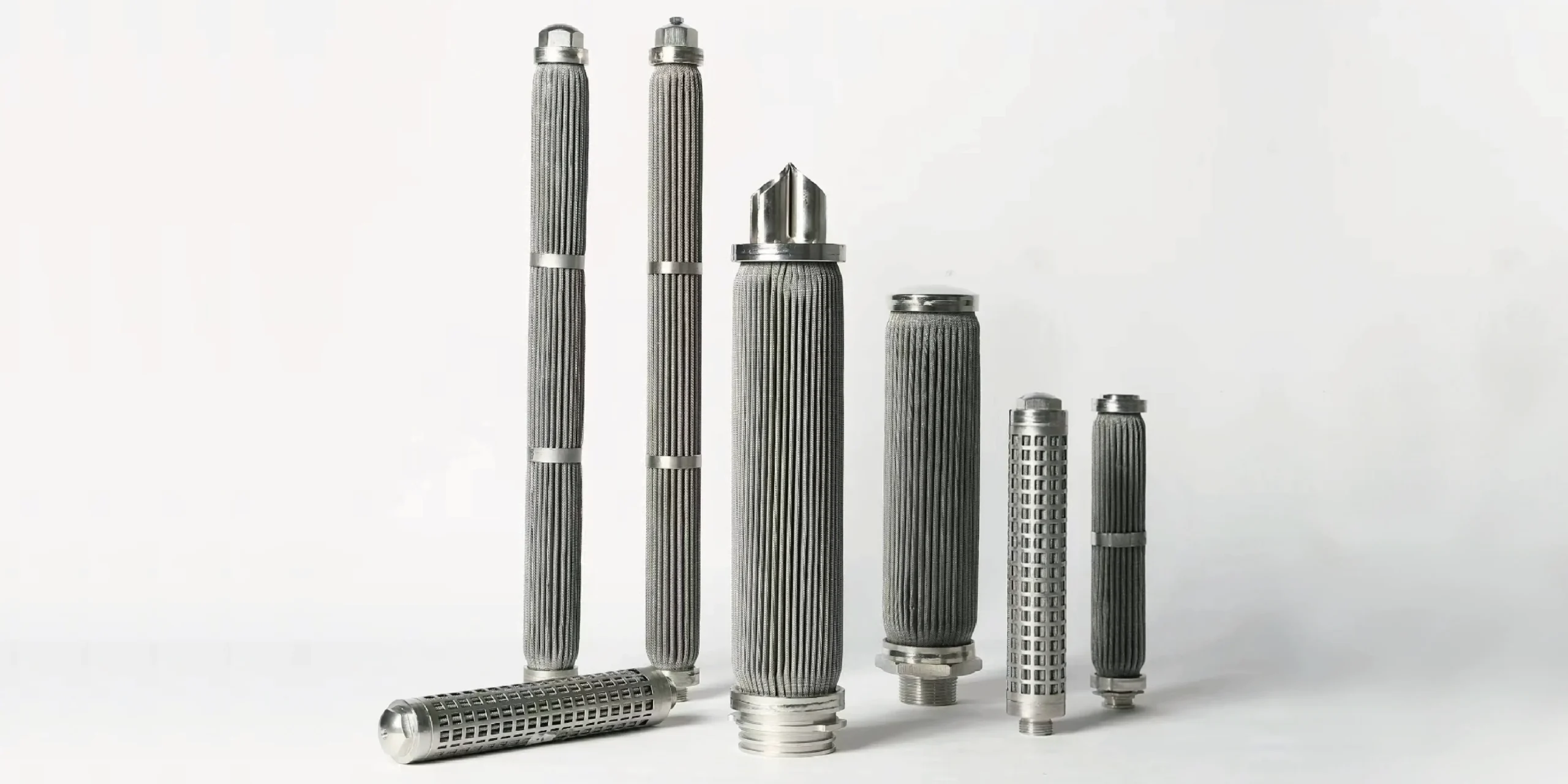
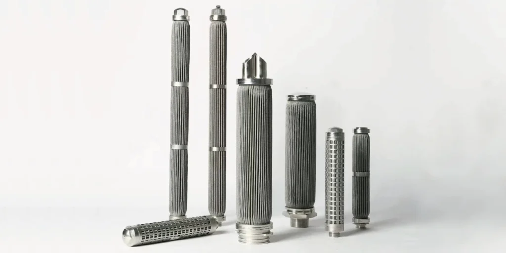
A replacement cartridge can have the expected length and diameter yet stop short of its seat, foul the center rod or leave the seal incorrectly engaged. The problem is often an incomplete dimension description rather than the nominal size itself. This guide explains which pleated filter cartridge dimensions to measure, where to place the reference points and what housing information is needed before ordering a replacement metal element.
Which Pleated Filter Cartridge Dimensions Matter Most?
Record the overall envelope, the dimensions between mounting and sealing references, the maximum outside diameter, the minimum relevant internal opening and the complete end-fitting geometry. Identify the seal arrangement and the mating housing surfaces. A nominal length and body diameter alone do not establish installation or sealing compatibility.
Separate three questions:
- Will the cartridge pass through the housing opening and clear internal components?
- Will its locating and retaining features engage in the intended positions?
- Will the specified seals contact the correct surfaces under the intended assembly condition?
Then verify filtration and operating requirements separately. A physically fitting cartridge is not automatically equivalent in removal performance, pressure-drop behavior, material compatibility or cleaning capability.
Why a “10-Inch” Cartridge Is Not a Complete Specification
Nominal length identifies a product category or ordering option. It does not, by itself, identify the physical endpoints used for the stated length. A supplier may distinguish the media section, body assembly, sealing references and full length including a projecting adapter or fin.
Do not convert the nominal label into an exact drawing dimension without checking its definition. Two elements placed side by side can have similar body lengths while their sealing shoulders or outlet spigots occupy different positions.
Pall's PREcart PP II data sheet illustrates how a catalogue can list adapter styles separately from nominal-length options. This product-family document is an example of why both fields matter, not a dimensional standard or interchangeability table for SINFT metal cartridges.
For a replacement, request or prepare a drawing with the endpoints marked. State units explicitly. Preserve the original identification, but let the verified assembly geometry determine what must be matched.
Define the Length Before Measuring It
“Length” needs a description. Use separate labels rather than sending one number that different people may interpret differently.
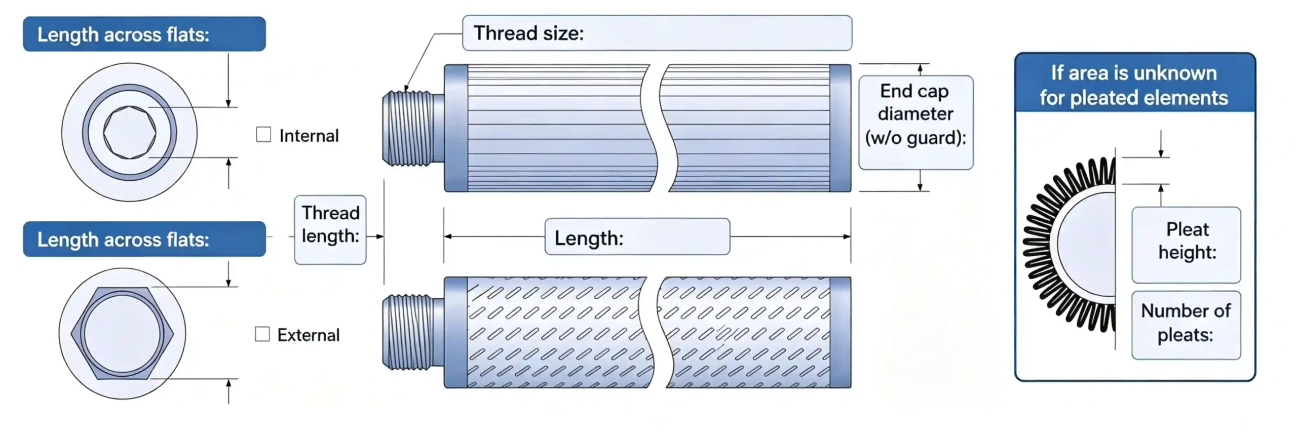
Overall length is the distance between the specified extreme ends of the complete element. State whether a removable seal, gasket, cap or other accessory is included. A projecting thread or locating fin may affect the overall envelope without being the surface that establishes sealing engagement.
Mounting or sealing reference length describes the axial relationship between the features that locate the cartridge and establish the relevant seal engagement. Identify the actual faces or shoulders. A dimension from a thread tip to an opposite cap is not necessarily the same as a seat-to-seat dimension.
Media length describes the filtering section under the chosen drawing definition. It should not silently replace overall or mounting length. End caps and welded transitions occupy space, and their dimensions can change while the visible pleated section remains similar.
For a gasketed assembly, distinguish an unloaded gasket measurement from a design dimension in the assembled condition. For a radial O-ring fitting, engagement depends on the bore, spigot and groove arrangement rather than simply compressing the entire cartridge axially. The applicable housing design must establish the intended assembly relationship.
A Practical Dimension Checklist
Measure only a removed, safe-to-handle element under the site's applicable isolation and handling arrangements. Use appropriate tools and avoid compressing or distorting the medium. Where access or condition prevents a reliable measurement, record the uncertainty instead of assigning a false precision.
| Feature to record | How to define it for a replacement review |
|---|---|
| Overall envelope length | Mark the two extreme reference points and identify included seals or removable parts. |
| Mounting/sealing length | Identify the locating shoulders or sealing faces and the relevant assembly condition. |
| Media/body section length | State which section is measured; keep it separate from adapter projections and overall length. |
| Maximum outside envelope | Include the largest cap, guard, weld projection, retaining band or other relevant feature. |
| Internal opening and passage | Identify where the opening is measured and any smaller restriction deeper inside. |
| Spigot, shoulder or seat | Record diameter, projection and position from a named reference face. |
| Threaded interface | Specify thread form, size, pitch, gender, engagement and sealing arrangement as applicable. |
| Locking or locating features | Record tabs, fins, keys, slots and their orientation relative to the fitting. |
| Seal and groove arrangement | Identify seal type, location, groove geometry and mating surface; separate observed from specified dimensions. |
| Housing and retention features | Establish insertion opening, seat, rod or standpipe and available axial space. |
Not every design needs every entry. The drawing should make the relevant dimensions unambiguous, with agreed tolerances on the features that control fit. Do not apply one arbitrary tolerance to the entire cartridge because it is convenient to inspect.
Outside Diameter: Measure the Largest Relevant Feature
The pleated body diameter is only one part of the outside envelope. An end cap, guard, weld bead or adapter can be larger. A cartridge can clear the cylindrical chamber yet fail to pass through a smaller insertion opening.
Record the maximum relevant dimensions and their locations. Check accessible positions around the circumference and along the length where variation matters. If an old guard is dented or a body is oval, record that condition separately rather than averaging it into a single intended design diameter.
Avoid squeezing exposed pleats with a measuring tool. A soft or thin section can deflect under contact pressure and give a misleading result. Appropriate tooling and measurement contact points depend on the construction.
Also establish space around the installed element. Adjacent cartridges, a housing wall or an internal support may limit the permissible envelope. Do not invent a universal clearance: the housing drawing and assembly requirements should define it.
Inside Diameter: An Open End Does Not Prove Rod Clearance
The visible opening may not be the smallest passage along the element. An internal shoulder, adapter, support tube or closed-end arrangement can limit insertion over a center rod or standpipe.
Record the opening diameter at the identified face and the relevant bore depth or internal restriction. If a center rod passes through the cartridge, review its diameter, straightness, attachments and retention arrangement with the element's actual passage. Do not infer a clear through-bore from an end photograph.
For a socket or spigot connection, insertion depth and shoulder position also matter. An element may appear to enter the fitting but stop before the sealing region is correctly engaged. Do not force it farther or assume that closure pressure should overcome an unidentified interference.
Where an internal dimension cannot be measured without damaging the old element, identify the gap and use a housing drawing, an approved sample investigation or another suitable method. Unknown geometry is a question to resolve, not a reason to manufacture an assumed value.
Identify the End Fitting, Not Just Its Catalogue Name
DOE, SOE, 222 and 226 descriptions can help identify a connection family, but a label does not replace the mating geometry. Review the supplier's actual adapter drawing, the opposite end and the housing socket or retention system.
DOE generally describes a double-open-end arrangement, while SOE describes a single-open-end arrangement. These descriptions do not, by themselves, establish every sealing face, gasket, projection or hold-down feature. An open-ended fitting with similar appearance can still differ in the features that control engagement.
| Connection arrangement | Fit details that need confirmation |
|---|---|
| Double open end | Both seating faces, bore, gasket arrangement and the housing's axial retention stack. |
| O-ring spigot or socket | Mating diameters, groove/seal arrangement, engagement depth and locating shoulder. |
| Locking adapter | Mating geometry plus tab dimensions, orientation, engagement and retention position. |
| Threaded end | Full thread designation, usable engagement, shoulder location and intended seal. |
| Flanged or custom welded end | Flange/face geometry, bolt or locating pattern where applicable, projections and seal interface. |
A threaded fitting deserves more than a diameter measurement. Different thread forms can look similar without being compatible. Determine the designation from reliable documentation or appropriate gauging; photographs and a rough outside diameter are insufficient. Also establish whether the design seals on a face, a separate seal or the specified thread arrangement.

The Seal Is Part of the Dimensional Match
A cartridge can be easy to insert yet seal incorrectly. The relevant dimensions depend on whether the design uses an axial gasket, radial O-rings, a metal gasket or another specified interface.
Record the seal location, specified seal identity if known and the geometry that positions it. Review the mating bore or face as well as the cartridge. A worn housing seat or damaged groove can prevent proper sealing even when a replacement element meets its drawing.
The Parker O-Ring Handbook, ORD 5700, treats seal selection and gland design as related engineering decisions. Seal cross-section, gland geometry, tolerances and application conditions need to be considered together. A generic squeeze percentage is not an appropriate substitute for the actual interface review.
An old O-ring may have swollen, hardened or taken compression set. Its measured dimensions are useful observations but do not necessarily identify the specified new seal. Keep the observed condition separate from the intended replacement requirement. Confirm compound compatibility and temperature duty separately from dimensional fit.
Do not solve an unexplained length or sealing mismatch by stacking extra gaskets, changing the hold-down arrangement or forcing the cover closed. Such a change can alter engagement and loading. Have the responsible engineer resolve the dimensional relationship and approve any design change.
Check the Housing Stack, Not Only the Loose Cartridge
The installed fit includes the cartridge, lower seat, upper retention arrangement, seals and any center rod or standpipe. Several individually plausible dimensions can combine into an incompatible assembly.
Start from an identified housing reference and establish where the element locates. Then review the available axial space, the intended retaining position and the relevant seal engagement. For a removable cover, include the features that actually contact or retain the element rather than assuming that the cavity depth alone controls fit.
For a multi-element housing, check whether all positions use the same sockets and retainers. A single old sample may not describe every location if the housing has been modified or contains mixed adapters.
The assembled relationship should be evaluated with the agreed tolerances and seal condition. There is no universal allowance that can be added to every nominal cartridge length. If the design basis is incomplete, resolve it before treating a trial insertion as acceptance. A trial fit, where authorized, does not prove sealing performance under operating conditions.
How to Prepare a Useful Measurement Package
Give the supplier one coherent set of references rather than unrelated measurements taken from different points.
- Identify the part and its condition. Record the old part number, housing identification, orientation and any damage or missing seals.
- Photograph the complete element and both ends. Include side and end views, with clear detail of grooves, threads, tabs and the opposite-end feature.
- Mark the measurement references. Use a sketch to show where each length, diameter and projection begins and ends.
- Record actual observations. State units, measurement condition and unresolved features. Separate sample measurements from approved nominal dimensions and tolerances.
- Add the mating information. Supply the seat, socket, center rod, hold-down or housing drawing needed to assess fit.
Photographs with a ruler can help establish scale but should not replace precise measurements of critical interfaces. Perspective, camera angle and hidden edges affect interpretation. Do not estimate a sealing groove or thread pitch from an angled image when the fit depends on that dimension.
Keep a deformed or incomplete sample identified as such. Copying wear, a bent guard or a missing gasket into a new drawing can reproduce the problem rather than the intended design. The filter element dimensional inspection guide explains how received measurements should be checked against agreed acceptance requirements.
What to Send SINFT Before Ordering
For a pleated filter cartridge replacement, provide the dimensioned drawing or measurement package, end photographs and available housing information. SINFT offers standard and custom end arrangements and can review drawing- or sample-based replacement requirements. Any missing fit-critical information needs resolution before the final manufacturing definition is approved.
Include the working medium, temperature, flow, required particle-removal performance, operating pressure and differential-pressure duties. For a hydraulic filtration application, also identify the actual fluid and relevant viscosity conditions where available. These inputs help establish functional suitability after the physical interface has been matched.
Specify the material, seal requirement, flow direction, cleaning method and required inspection documents. If the old medium is unknown, say so; a dimensionally matching metal body does not establish an equivalent filtration layer or structural rating.
Use the pleated cartridge selection guide for the broader selection sequence and the industrial cartridge sizing guide for flow and area review. For drawing-based supply, visit the custom filter manufacturer page and send the package through the contact inquiry form.
Frequently Asked Questions
Is a nominal 10-inch cartridge exactly 254 mm overall?
Not necessarily. The nominal category does not establish which physical endpoints a manufacturer uses or whether a projecting adapter, fin or removable seal is included. Confirm the actual drawing and its length definition. Record overall envelope length separately from mounting references and media length. A unit conversion of the nominal label cannot replace the dimensional definition required for the mating housing.
Should the old gasket be included when measuring length?
Record whether the measurement includes it, and identify its condition. An unloaded gasket, a compressed assembly and a cartridge without the gasket represent different measurements. A used gasket may no longer represent the specified new component. The drawing should define the required reference faces and assembly condition, with the intended replacement seal identified separately rather than silently copied from a worn sample.
Are two cartridges interchangeable if their body diameters match?
No. End caps, guards, welds and adapters can create a larger outside envelope, while sealing shoulders and internal passages may differ. Check the insertion opening, center rod or standpipe, retaining arrangement and complete interface geometry. Physical fit also does not establish equivalent filtration performance. Dimensions, seal compatibility, media and operating capabilities must each be reviewed for the intended replacement duty.
Does a 222 or 226 label fully define the connection?
It helps identify an interface family, but the actual adapter, opposite end and mating housing still need confirmation. Review dimensions, seal arrangement, engagement depth and any locking features against the appropriate drawings. Do not approve a replacement from the code or photograph alone. Similar-looking fittings can leave important questions about locating shoulders, retention and sealing engagement unanswered until the assembly is reviewed.
Can inside diameter be measured only at the open end?
That measurement describes the opening at the identified location, not necessarily the full internal passage. A shoulder, support tube, adapter or closed-end arrangement can restrict a center rod or standpipe farther inside. Establish the relevant bore depth and restrictions for the actual housing. Where access is limited, document the unknown and agree a suitable verification method instead of assuming a clear through-bore.
Can dimensions be estimated from photographs?
Photographs are useful for recognizing construction and communicating locations, but perspective and hidden features limit accuracy. Include clear side and end views with scale where helpful, then supply measured critical dimensions and their reference points. Groove geometry, thread designation and sealing engagement should not depend on visual estimation. Mark any inaccessible or uncertain feature so the supplier can identify what still needs verification.
Can a damaged old cartridge be used as the manufacturing master?
It can provide useful information, but its damage and wear must be identified. A bent guard, deformed cap, swollen seal or missing component may not represent the intended design. Compare the sample with available housing information, records and approved dimensions. Resolve which features should be reproduced before manufacture rather than treating every observed measurement on the old element as the correct specification.
What is the minimum useful package for a replacement inquiry?
Send a dimensioned sketch with reference faces, clear photographs of both ends, overall and mating dimensions, seal information and available housing details. Include the old identification and operating duty, and identify unknowns. A sample can support the review where appropriate, but it does not remove the need to establish intended fit and performance. Critical uncertainties should be resolved before the final manufacturing drawing is approved.
Final Thoughts
The right dimensional match begins with clear reference faces and the complete mating assembly. Measure the envelope, locating features and sealing interfaces separately, then check them against the housing and intended seal condition. Send SINFT a marked drawing or measurement package with your operating requirements so the replacement review can address installation, sealing and filtration suitability together before manufacture is approved.