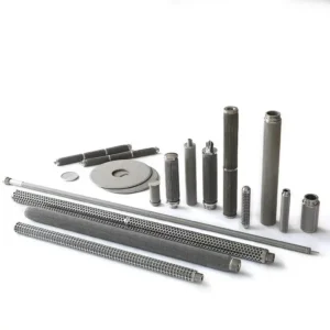
The old filter measures 60 mm across and 250 mm long. Those two numbers can still produce a replacement that bottoms out before the seal seats. When recording sintered mesh filter dimensions, start with how the element sits in the housing. A shoulder, flange, rim, or frame may control the fit. Once you identify that surface, the rest of the measurements have a reference the supplier can use.
Which Sintered Mesh Filter Dimensions Should You Measure?
Record the locating face, insertion depth, outside envelope, sealing position, and connection details. Then add the dimensions specific to the shape. For a tube, those may be the bore and end fittings. For a disc, they may be the rim thickness and central opening. For a cone, record the two end diameters and axial height. For a panel, measure the outside frame and the opening the mesh covers.
Ask the supplier to confirm which values govern fit and which need further review. Measurements taken from a worn sample describe that sample in its current condition. A drawing or a sound mating part can provide better evidence for the original design.
Start With the Face That Locates the Filter
Identify the surface that stops the element in its installed position. On a flanged tube, this could be the underside of the flange where it meets the support plate. On a disc, it might be the rim resting on a ledge. On a panel, it could be the frame face against the gasket. Mark that surface on a sketch and use the same reference for every related dimension.
Record the length below the locating face, the projection above it, and the clear space available on both sides. Overall length can help identify a part, but it cannot tell you how much of that length occupies each side of the mount. Include retaining nuts, weld beads, lifting handles, or other protrusions if they limit installation or removal.
For example, two assemblies may both be 250 mm long. If the original has 230 mm below its seating face and the replacement has 235 mm, the replacement needs 5 mm more room inside the housing. If only 233 mm is available from that face to the nearest obstruction, it will stop 2 mm short of seating. These are illustrative dimensions. The actual clearance depends on the assembly drawing and its tolerances.
Measurements by Element Shape
Sintered wire mesh can be fabricated in different shapes. Porvair’s sintered mesh composite overview shows examples in sheet, cone, and cylinder form. Each shape needs its own set of measurements for a replacement quote. Record the filter media separately from the shape. The sintered filter working principle guide explains how wire mesh differs from other sintered media.
| Element form | Dimensions to record | What can cause a mismatch |
|---|---|---|
| Tube or cartridge | Body OD and bore ID, overall length, length from the seating face, end fittings and seal location | The body enters the housing but an end cap, shoulder, or weld contacts a stop early. |
| Disc | Outside diameter, rim and mesh thickness, center hole or hub, gasket land, and any mounting holes | A disc with the right OD sits proud because the assembled rim is too thick. |
| Cone or truncated cone | End diameters, axial height, mounting flange or collar, tip clearance, and taper direction | The flange matches but the body interferes with a reducer or the tip sits too close to an outlet. |
| Flat panel | Outside length and width, frame thickness, clear opening, corner shape, fastener spacing and orientation | The panel fits the recess, but an offset hole pattern or narrow gasket land prevents it from seating. |
Tubes and Cartridges
Take diameter readings at several axial locations and in more than one direction where the body may be oval. Record the largest obstruction separately from the mesh OD. A weld seam, reinforcing collar, or end cap may determine what passes through the opening. Record which end is open and how far a mating tube or stem enters the bore.
For a threaded end, identify whether the thread is internal or external. Capture its pitch and engagement length, and confirm the thread designation against the mating part or drawing. A caliper reading across a thread helps describe the sample but cannot establish the thread standard by itself. Record the sealing face separately. Some connections seal at a gasket or O-ring even though a thread holds the parts together.
Discs, Cones, and Panels Need Their Own Measurements
Discs. Measure the full OD, the supported rim or weld ring, and the part of the mesh exposed to flow. Record rim thickness separately from mesh thickness. If there is a central opening, identify whether it locates on a shaft, acts as an outlet, or simply clears hardware. For drilled patterns, show the number of holes, their diameter, and their location from the center or another defined feature. The sintered filter disc product page shows the commercial product family.
Cones. Mark the large and small ends on a section view, then measure the axial height between defined planes. Label any angle as the included angle or the angle from the centerline. The sloping wall length does not describe how far the assembly projects into the pipe. Show whether the small end is open or closed and note the distance from the mounting face to the furthest protrusion.
Panels. Measure the outer frame independently of the open mesh window. Show mounting hole offsets from two adjacent edges. Mark asymmetric corners and which face meets the gasket. Include any ribs or support bars that project into the housing, and identify their side relative to flow. The approved drawing should make orientation obvious even when the panel looks nearly symmetrical.
Confirm the Seal and the Mating Part
Identify whether the element seals against a flat face, inside a bore, or around a spigot. Note which component contains the groove or gasket seat. For an O-ring connection, record the groove location and accessible gland dimensions, the mating bore or shaft, and any specified seal part number. The Parker O-Ring Handbook provides background on why the seal and gland must be considered together. Use the original assembly requirements or an approved seal design for acceptance.
A used gasket can be flattened and an old O-ring can be swollen or worn. Record what you found, but flag the original seal size or compound as unknown if you cannot verify it. Share a close-up of the seat and a photo showing the seal's installed orientation. A dry fit can show whether the part clears the housing. It does not establish that the seal will hold under operating conditions.
In a self-cleaning or backwash filter assembly, also check the clearance to any collection tube or cleaning hardware. Mark normal flow and the reverse cleaning direction on the sketch. That information helps the supplier review whether the proposed layer stack, support, and mounting arrangement suit the duty.
Put Measured Values and Design Requirements on Separate Lines
A sample that has been removed from service can provide a starting sketch. Label any dent, worn seating face, oval opening, or repaired weld so that the supplier can identify measurements affected by damage. Use the housing or original drawing to resolve those dimensions before approving manufacture. If a mating feature cannot be accessed, mark it as unverified and explain where it is.
| Information to send | What to include |
|---|---|
| Part identification | Equipment model, old part number, drawing revision, and photos of the complete element and its ends |
| Fit sketch | Units, locating face, orientation, envelope, insertion depth, mating dimensions, and the seal or fastener position |
| Evidence for each critical value | Drawing value, sample reading, housing measurement, or an open item that needs confirmation |
| Operating conditions | Process fluid, flow, temperature, operating and differential pressure, flow direction, and cleaning method |
| Filtration and acceptance | Known mesh construction, required retention and rating basis, quantity, and the agreed fit checks for the finished element |
Where you know a drawing tolerance, include it with the nominal dimension. Where you only have a measurement, report it as observed and agree the allowed variation with the supplier. For incoming checks after manufacture, see the filter element dimensional inspection guide.
How SINFT Can Help With a Replacement
SINFT offers sintered mesh filter elements in tube, cartridge, disc, cone, panel, and custom assembly forms. For a custom filter replacement, share the drawing, sample information, housing sketch, and operating conditions together. If drawings and measurements disagree, highlight the affected feature and identify which source should govern before approving a replacement drawing.
A useful first request is a drawing review with the seating face and critical interfaces marked. If the part number or filtration specification is unavailable, describe the current service and any known performance issue so the review can address both physical fit and filtration requirements. Send your measurements and service details to start the review.
Frequently Asked Questions
Are outside diameter and overall length enough to match a replacement?
Usually the supplier also needs the seating position, insertion depth, end connection, and seal arrangement. Two filters with the same outside diameter and overall length can put the seal at different heights or have different end projections. A dimensioned sketch of the installed interface will usually answer more questions than another photo of the full element.
Where should I measure the length of a filter with a flange?
Record overall length, then measure from the face that seats against the housing to the deepest part of the element. Record the projection on the other side if it affects cover or fastener clearance. Indicate which flange face you used on a section sketch so the supplier can distinguish insertion depth from the height of the entire assembly.
Can a supplier reproduce an element from a bent sample?
A bent sample can still show the general construction, fittings, and some undamaged dimensions. Mark the damaged region and ask the supplier to verify affected values against the housing, an original drawing, or a sound spare. Measure the mating parts whenever possible. A supplier should confirm the intended profile on a drawing before the replacement is made.
How should I record the thickness of a sintered mesh disc?
Report the thickness of the mesh laminate separately from the total thickness at the rim or frame. If there is a gasket, show its location and whether any reported thickness includes it. The rim thickness may determine how a retainer closes, while the laminate thickness describes the filtering structure. Note exactly where each measurement was taken.
Do I need an angle measurement for a conical filter?
End diameters and axial height often give the supplier enough information to sketch a straight taper, provided the reference planes are clear. If the drawing specifies an angle, label whether it is the included angle or the angle from the axis. Also show any straight collar or flange because it may sit outside the taper dimensions.
Can I use my measurements as manufacturing tolerances?
Use measurements to document what you found and use the approved drawing to define what the new part must satisfy. Caliper resolution, worn surfaces, and variation around a part can all affect readings. When a tolerance is missing, identify the dimensions critical to fit and ask the supplier to agree suitable limits based on the mating assembly.
Does a dimensionally identical element have the same filtration performance?
A matching envelope establishes only part of the specification. Verify the mesh grade, layer arrangement, support, effective area, and flow direction. Compare the required retention and allowable pressure drop under the intended service conditions. If the original media specification is unavailable, identify the fluid and particles and agree what performance the new element must demonstrate.
What should I send first if I have no drawing?
Send photos of the complete element, both ends, and the housing seat. Add a sketch showing the locating face, insertion depth, outside diameter or frame dimensions, and connection details. Include units and mark anything you could not measure. A nameplate photo or part number can help the supplier identify which information still needs confirmation.
Final Thoughts
Start at the surface that locates the element, then measure the envelope, seal, and connection from clear references. Use the housing and original drawing to check anything the old part cannot tell you. A short sketch that separates measured dimensions from open questions gives SINFT a better basis for reviewing a replacement and agreeing what the finished element must fit.