If your filter loads too quickly, cleans poorly, or lets fine contaminant pass, the problem may not be only the micron rating. The capture mechanism matters. A surface medium and a depth medium can share a similar nominal rating but behave very differently in pressure drop, dirt loading, cleaning recovery, and inspection.
Direct Answer: Surface Filtration vs Depth Filtration
Surface filtration vs depth filtration is mainly a choice between where particles are captured and how the filter should handle contaminant loading. Surface filters retain most particles at or near a defined upstream surface. Depth filters retain particles through a three-dimensional network of flow paths within the medium.
Choose surface filtration when stable openings, cake release, visual inspection, or strong backwash cleaning are priorities. Choose depth filtration when your process has a broad particle distribution, fine contaminant, or a higher dirt load that should be distributed through the media volume. The correct choice still depends on required retention efficiency, fluid properties, flow, allowable differential pressure, cleaning method, and element construction.
What Is Surface Filtration?
Surface filtration captures most retained particles on the upstream face of the filter medium. Particles too large to pass the controlling openings remain on the surface and can form a filter cake as loading continues.
Common industrial surface media include woven wire mesh, perforated plate, wedge wire, and the controlled filtration layer in a multi-layer sintered mesh. The openings may be square, Dutch woven, slotted, round, or another engineered geometry.
Surface filtration is often selected when the buyer needs:
- A defined aperture or slot geometry
- Separation of relatively coarse or consistently sized particles
- Removal of a deposited cake by backwash, scraping, air blowing, or other compatible cleaning
- A rigid medium that can be inspected after cleaning
- Repeatable fit in a reusable metal element
The term “surface” does not mean that every particle stops on one perfectly flat plane. Some particles can enter an opening, bridge across adjacent openings, or become embedded in a cake. The classification describes the dominant retention location and loading behavior.
What Is Depth Filtration?
Depth filtration captures particles at multiple locations through the thickness of a porous medium. Fluid follows interconnected and often tortuous paths, while particles are retained by mechanisms that can include size exclusion, interception, inertial effects, diffusion, and surface interactions.
Depth media can be made from fibers, powders, bonded granules, cellulose, polymers, glass fibers, or metal fibers. In reusable high-temperature industrial filtration, sintered metal fiber felt is an important depth medium because randomly laid fibers form a porous three-dimensional network.
Depth filtration is often selected when the process needs:
- Contaminant storage through the media volume
- Retention of a broad distribution of particle sizes
- Fine-particle capture that cannot be described by one screen opening alone
- Protection of a downstream polishing filter, membrane, nozzle, valve, or process
- A gradient structure with coarser upstream and finer downstream regions
Depth filtration does not automatically mean disposable filtration. A stainless steel fiber-felt element may be cleaned and reused when its construction, contaminant, and cleaning procedure allow it. However, aggressive reverse-flow cleaning is not automatically suitable for every depth medium.
Surface Filtration vs Depth Filtration: Key Differences
The practical difference is not simply “coarse versus fine.” It is the combination of retention mechanism, loading pattern, cleanability, mechanical structure, and test method.
| Selection factor | Surface filtration | Depth filtration |
|---|---|---|
| Dominant capture location | At or near the upstream surface | Through the thickness of the medium |
| Typical pore structure | More defined apertures or slots | Interconnected pores with multiple flow paths |
| Loading behavior | Surface deposit or cake develops | Contaminant occupies available media depth |
| Particle distribution | Often effective for a narrower or coarser distribution | Often useful for broad distributions and fine contaminant |
| Cleaning behavior | Deposited solids may be easier to release from the surface | Embedded particles can be more difficult to remove completely |
| Inspection | Surface and openings can often be inspected directly | Internal loading is harder to inspect visually |
| Typical metal media | Woven mesh, sintered mesh control layer, wedge wire, perforated plate | Sintered metal fiber felt and some porous metal structures |
| Rating interpretation | May be related to an aperture, but efficiency still requires a defined test | Usually depends on efficiency under a specified test, not one geometric opening |
| Best use case | Stable opening, cake recovery, backwash, rigid reusable construction | High dirt load, fine polishing, broad particle capture, gradient filtration |
These are selection tendencies, not universal performance guarantees. A poorly sized surface filter can blind rapidly, while a poorly matched depth filter can load internally and become difficult to regenerate.
How Does a Surface Filter Capture Particles?
A surface filter begins with its controlling openings, then its behavior changes as particles accumulate. Early retention is influenced by aperture size, particle shape, deformability, flow direction, and the probability that a particle encounters an opening in a passable orientation.
As retained particles bridge and form a cake:
- The effective openings can become smaller.
- Retention of finer particles may increase.
- Differential pressure normally rises.
- Flow can redistribute across the remaining open area.
- Cleaning becomes necessary when the approved terminal condition is reached.
This means a surface filter’s operating performance cannot be predicted from mesh count or slot width alone. Open area, wire diameter, layer support, element area, fluid viscosity, and contaminant behavior also matter.
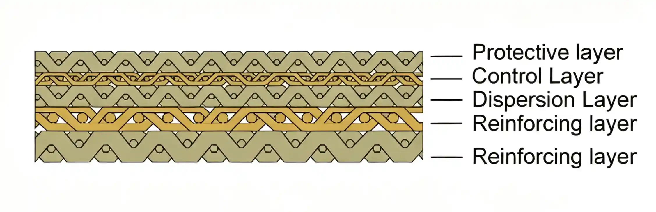
SINFT sintered mesh filter elements use multi-layer woven metal mesh joined into a rigid medium. The control layer defines the filtration function, while other layers protect, distribute flow, and reinforce the structure. Final performance still depends on the selected weave, layer arrangement, dimensions, flow direction, and housing.
How Does a Depth Filter Capture Particles?
A depth filter provides many possible capture sites along an internal flow path. Larger contaminant may be retained in the upstream region, while smaller particles can travel farther before being captured.
A graded structure can use:
- A more open upstream region to accept larger particles
- Intermediate layers to distribute the load
- A finer downstream region to provide the required final retention
- Support layers or protection mesh to maintain shape
This use of media volume is why depth filtration is often considered for high dirt-loading service. However, dirt-holding capacity must be established under a defined test. It cannot be inferred accurately from media thickness or porosity alone.
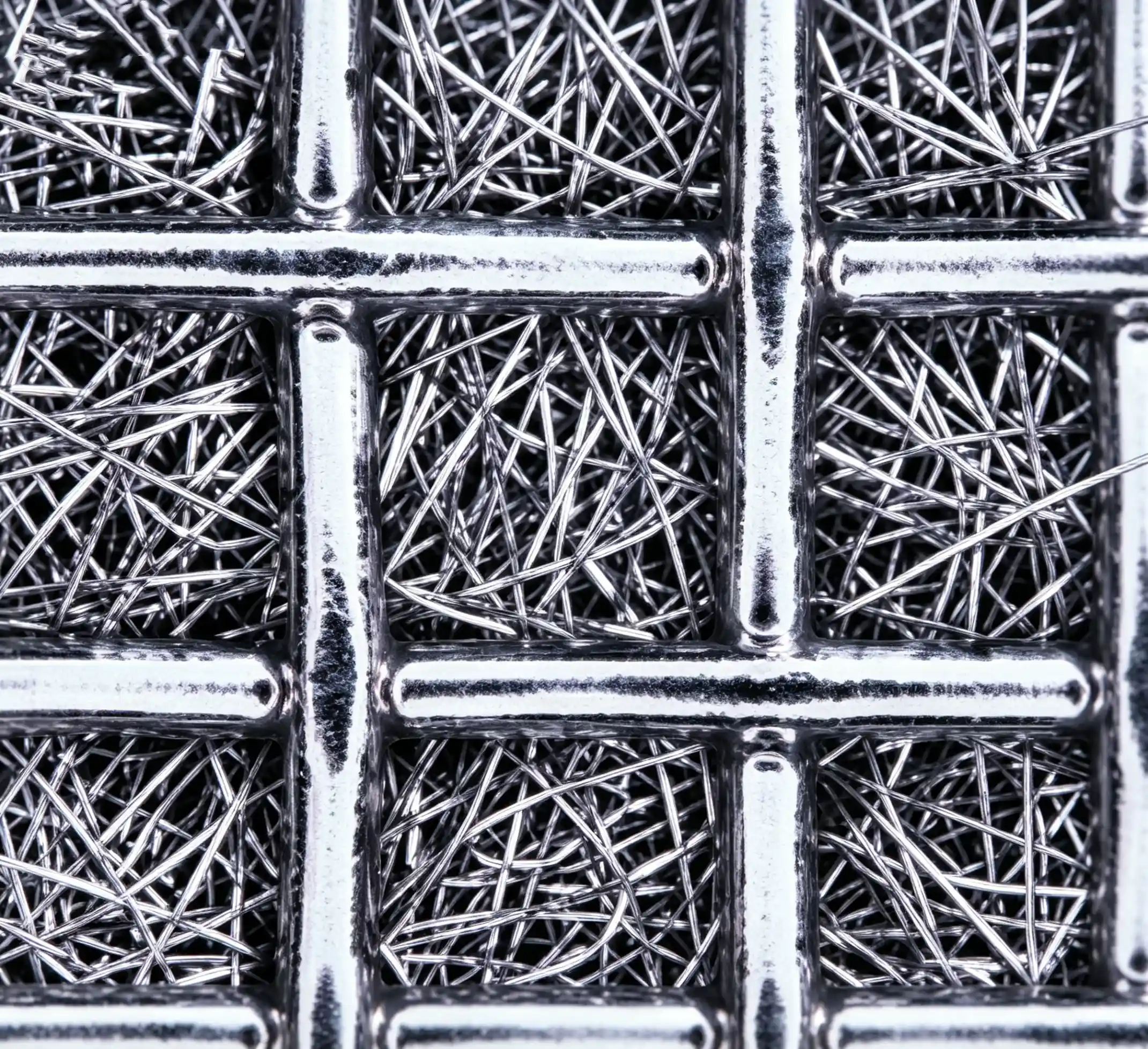

SINFT sintered fiber felt filters use a random metal-fiber matrix and can be supplied with no protection mesh, a single protection mesh, or double protection mesh. The appropriate construction depends on retention requirements, differential pressure, flow direction, mechanical support, and cleaning method.
Which Type Has Higher Dirt-Holding Capacity?
Depth media often provide more internal contaminant-storage volume, but dirt-holding capacity is a tested property of the complete element—not a guaranteed result of the word “depth.” Particle size distribution, concentration, shape, fluid, flow, element area, media grade, and terminal differential pressure all influence the measured capacity.
For hydraulic filter elements, ISO 16889:2022 describes a multi-pass method that evaluates particulate removal, contaminant capacity, and differential-pressure characteristics under stated test conditions. Its results apply to the tested element and defined hydraulic test; they should not be transferred directly to steam, compressed gas, polymer melt, or unrelated process filters.
When comparing supplier data, ask whether “dirt-holding capacity” means:
- Mass of standardized test contaminant to a defined terminal ΔP
- Process solids retained before a production endpoint
- A calculated media-volume value
- A relative comparison against another grade
Only the first two can support a meaningful operating comparison when the test conditions are disclosed.
Which Type Has Lower Pressure Drop?
Neither surface nor depth filtration always has lower pressure drop. Clean and loaded differential pressure depend on permeability, effective area, thickness, aperture geometry, supports, pleats, housing, flow, viscosity, density, temperature, and contaminant loading.
A surface filter with open mesh can have low clean resistance, but a surface cake may raise ΔP as available area closes. A high-porosity depth medium can distribute loading and delay surface blinding, but its longer internal flow path also contributes resistance. Element construction can outweigh the broad media category.
Compare pressure drop using:
- The exact element and housing configuration
- The same fluid or an approved viscosity correction
- The same temperature and flow condition
- Clean-element ΔP
- Loading behavior to a stated terminal ΔP
- The same retention-efficiency requirement
For hydraulic assemblies, ISO 3968:2017 provides a method for evaluating differential pressure versus flow at different flow rates and viscosities. Outside that scope, request an equivalent curve and clearly stated test conditions for the actual process filter.
Can Micron Ratings Be Compared Directly?
Do not compare a surface-filter aperture with a depth-filter micron rating unless the rating methods are compatible. A screen opening is a geometric feature. A depth-filter rating is normally based on measured particle retention or efficiency under stated conditions.
Terms such as nominal, absolute, retention rate, beta ratio, and pore size are not interchangeable. Ask the supplier to identify:
- Test method and test fluid
- Challenge-particle distribution
- Upstream and downstream measurement method
- Efficiency or beta ratio at the stated particle size
- Flow rate and viscosity
- Clean or loaded condition
- Whether the value applies to media, element, or complete assembly
Bubble-point testing also needs careful interpretation. ISO 2942:2018 states that first bubble point is used for fabrication-integrity assessment and information; it is not, by itself, a functional filtration rating, efficiency, or retention-capacity result.
Which Filtration Method Is Easier to Clean?
Surface filtration is generally easier to regenerate when contaminant remains on an accessible, rigid surface and the cake releases cleanly. Backwash, air blowing, spraying, ultrasonic cleaning, or compatible chemical cleaning may remove the deposit, depending on the medium and process.
Depth media can also be reusable, but cleaning becomes harder when particles penetrate deeply, deform, dissolve and reprecipitate, or adhere to fibers. A cleaning method that restores flow may still leave contaminant that changes retention or differential pressure.
Before specifying a reusable element, confirm:
- Whether solids are hard, soft, fibrous, sticky, or gelatinous
- Whether the process fluid dries or polymerizes during shutdown
- Which cleaning fluids are chemically compatible
- Whether reverse flow could deform the medium
- How cleanliness and integrity will be verified after cleaning
- The acceptable post-cleaning flow and bubble-point criteria
For aggressive backwash service and stable pore geometry, rigid sintered mesh is often the better starting point. For higher dirt loading and distributed fine-particle capture, sintered fiber felt may be the better starting point. Final selection should be validated against the actual contaminant and cleaning cycle.
Sintered Mesh vs Sintered Fiber Felt
Sintered mesh is primarily chosen as a rigid surface-filtration medium, while sintered fiber felt is primarily chosen as a high-porosity depth-filtration medium. Both can be made into reusable stainless steel elements, but they solve different loading and cleaning problems.
| Engineering requirement | Sintered mesh starting point | Sintered fiber felt starting point |
|---|---|---|
| Stable controlling opening | Strong fit | Depends on tested media grade |
| Rigid shape under demanding service | Strong fit | Requires appropriate support and construction |
| Aggressive backwash or surface cake release | Usually preferred | Confirm regeneration feasibility |
| High dirt load distributed through media | Limited by selected layers and area | Usually preferred |
| Broad fine-particle distribution | Depends on weave and rating | Often a strong fit |
| Direct inspection of controlling surface | Easier | Internal loading is harder to inspect |
| Gas, steam, or polymer-melt depth filtration | Application dependent | Often a strong fit |
| Custom tube, disc, cartridge, or welded assembly | Available | Available |
The correct comparison must use the same retention target, element dimensions, flow, fluid, temperature, differential-pressure limit, and cleaning objective.
In polymer melt filtration, for example, media selection also depends on melt viscosity, gel or agglomerate loading, residence time, temperature, screen-change strategy, and allowable pressure rise. The application name alone does not determine whether a surface or depth medium is correct.
Can One Filter Combine Surface and Depth Filtration?
Yes. Industrial elements can combine stages or layers so that surface and depth mechanisms work together. Examples include a coarse surface prefilter ahead of a depth element, a protection mesh around fiber felt, or a multi-layer element with different pore structures.
A staged system can:
- Remove large debris before a fine depth stage
- Protect expensive polishing media from premature loading
- Make the upstream stage easier to clean
- Separate recoverable solids before final clarification
- Reduce the loading rate on downstream valves, nozzles, or membranes
For coarse pipeline protection, basket and Y strainers are common upstream options. SINFT’s basket strainer vs Y strainer guide explains how access, debris load, footprint, and cleaning frequency affect that prefiltration decision.
How to Choose Between Surface and Depth Filtration
Choose the filtration mechanism only after defining the contaminant, retention target, operating window, and cleaning strategy. Use this sequence.
1. Characterize the contaminant
Record the particle-size distribution, concentration, shape, hardness, compressibility, stickiness, and whether fibers or gels are present. A single “largest particle” value is not enough.
2. Define the required downstream result
State whether the filter protects equipment, clarifies a product, recovers solids, controls a cleanliness code, or performs final polishing. Define efficiency using a recognized or mutually agreed test.
3. Calculate the operating window
Provide normal, minimum, and maximum flow; operating and design pressure; clean and terminal differential pressure; temperature; viscosity; density; and gas inlet pressure where relevant.
4. Decide whether the solids should form a cake
If the cake should remain accessible for discharge or backwash, surface filtration is often favored. If the goal is to distribute a broad fine-particle load through the medium, depth filtration is often favored.
5. Define the cleaning and verification method
Specify backwash, ultrasonic, chemical, steam, air blowing, or replacement. Include acceptance criteria after cleaning rather than assuming that visible cleanliness proves restored performance.
6. Select material and element construction
Confirm corrosion compatibility, media support, flow direction, end connection, seal, welding, dimensions, and housing fit. SINFT’s custom filter manufacturing service can review a drawing, old element, sample, housing dimensions, or required connection.
7. Validate with representative testing
When operating risk is high, compare candidate elements with representative fluid, contaminant, flow, temperature, and terminal conditions. Use test results for the complete element rather than relying only on generic media descriptions.
What Buyers Should Confirm Before RFQ
A useful RFQ describes the process and acceptance criteria, not just the filter material. Provide:
- Working liquid, gas, steam, oil, or polymer.
- Contaminant composition and particle-size distribution.
- Solids concentration or expected loading.
- Required efficiency, micron rating, aperture, or slot width.
- Normal, minimum, and maximum flow rate.
- Operating and design pressure.
- Allowable clean and terminal differential pressure.
- Operating, start-up, and cleaning temperature.
- Viscosity and density at the relevant temperatures.
- Required surface or depth filtration behavior.
- Cleaning method, direction, pressure, and cycle.
- Element OD, ID, length, end connection, seal, and flow direction.
- Existing housing, drawing, sample, photo, or part number.
- Required material certificates and inspection records.
These details allow SINFT to compare sintered mesh, sintered fiber felt, pleated metal media, or a staged construction without assuming performance conditions that have not been confirmed.
How SINFT Can Help With Surface and Depth Media Selection
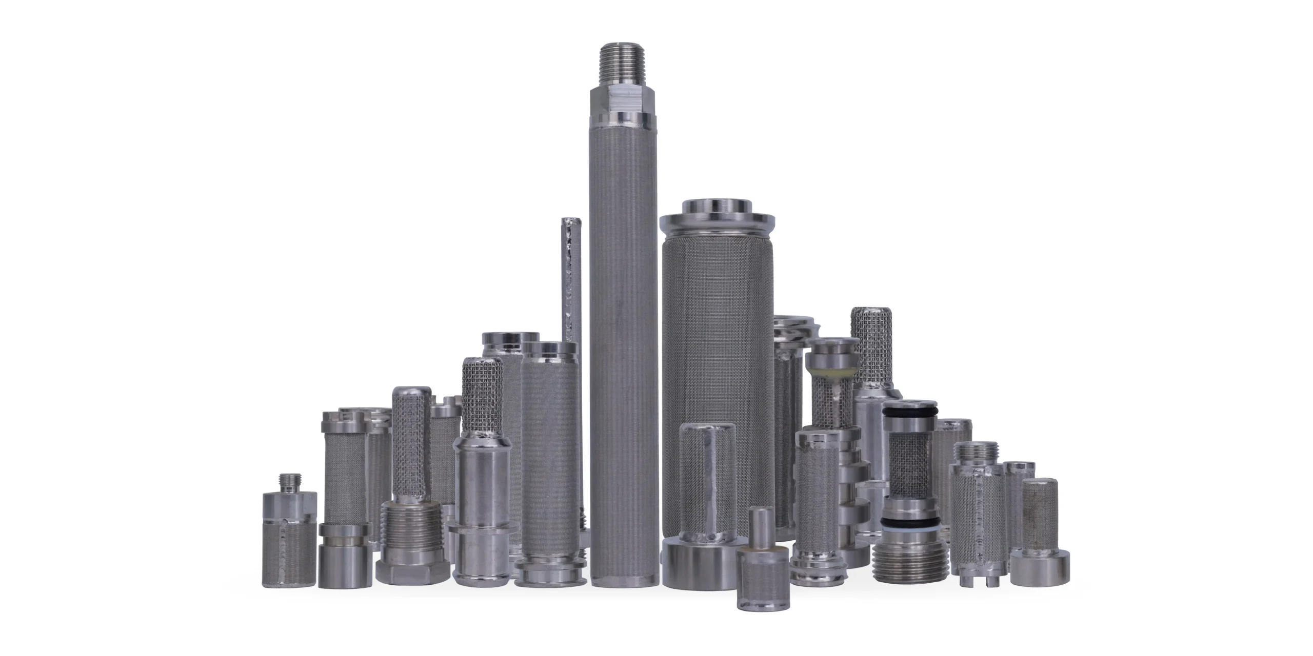
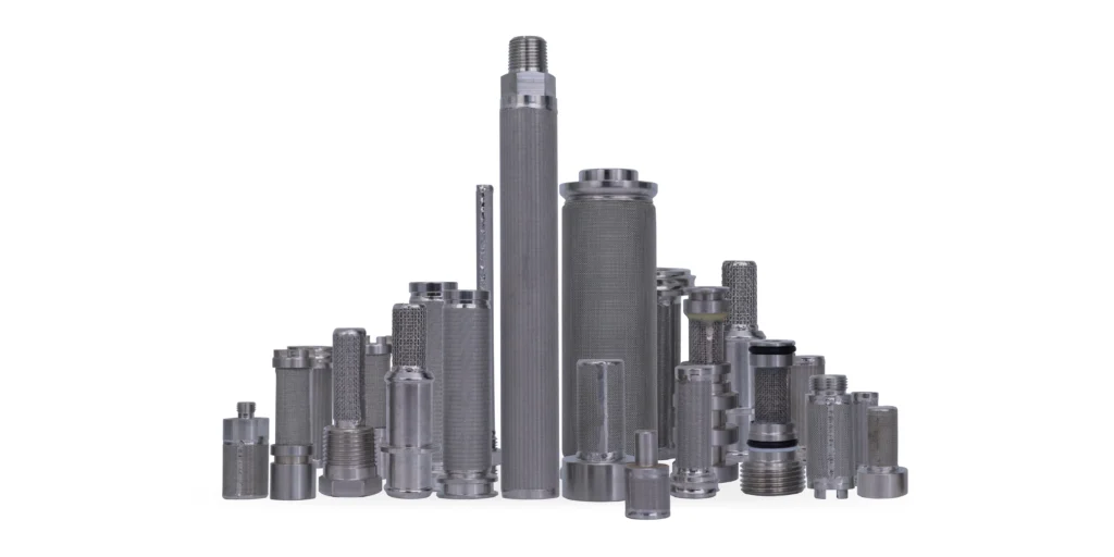
SINFT can manufacture both surface-filtration and depth-filtration stainless steel elements, including sintered mesh filter elements, sintered fiber felt filters, pleated metal cartridges, baskets, discs, tubes, cones, and custom welded assemblies. The correct choice depends on how your contaminant loads, whether it should release during cleaning, and how the finished element fits the housing.
For rigid surface filtration, SINFT can review sintered mesh, woven mesh, perforated plate, wedge wire, or basket-type constructions. For depth loading and fine contaminant distribution, SINFT can review sintered metal fiber felt grades and support structures. If the duty is not clear, drawings, samples, flow data, contaminant details, and cleaning requirements help compare the two mechanisms before manufacturing.
Frequently Asked Questions
What is the main difference between surface and depth filtration?
Surface filtration retains most particles at or near the upstream media face. Depth filtration retains particles at multiple locations through a three-dimensional porous medium. In practice, this changes how the filter loads, how pressure drop rises, how easily the element can be inspected, and whether cleaning or backwash can restore performance after service.
Is depth filtration always finer than surface filtration?
No. Either type can be engineered for different retention levels. A fine surface medium and a depth medium may both be supplied with micron ratings, but those ratings may come from different definitions or tests. Compare tested efficiency, rating method, flow, pressure drop, dirt-holding capacity, and cleaning behavior rather than the labels “surface” and “depth” alone.
Does depth filtration have higher dirt-holding capacity?
Depth media often provide more internal storage volume, but actual dirt-holding capacity depends on the complete element and defined test conditions. Media thickness, porosity, contaminant type, flow, terminal differential pressure, and cleaning method all matter. Do not assume a depth medium will last longer unless the comparison uses the same contaminant, flow condition, retention target, and endpoint.
Can surface and depth filters be cleaned and reused?
Both can be reusable when the media, contaminant, element construction, and cleaning method are compatible. Surface deposits are generally easier to inspect and remove than particles embedded deep in a medium. Depth elements may still be cleaned, but the supplier should define the cleaning method and the post-cleaning acceptance criteria, such as flow recovery, bubble point, or visual inspection.
Is sintered mesh a surface filter or a depth filter?
Multi-layer sintered wire mesh is primarily used as a rigid surface-filtration medium because a controlling mesh layer defines retention. Other support and dispersion layers still affect flow and structure. If your process needs high dirt loading through a porous matrix rather than surface cake control, compare sintered mesh with sintered fiber felt before finalizing the element.
When should I choose sintered fiber felt instead of sintered mesh?
Choose sintered fiber felt when the process benefits from depth loading, high porosity, broad fine-particle capture, or distributed contaminant storage. It may be useful in gas, steam, polymer melt, or high-temperature filtration when the grade and support structure match the duty. Confirm cleaning recovery carefully, because particles can embed inside the fiber matrix.
Final Thoughts
Surface or depth filtration should be selected from the actual contaminant distribution, required efficiency, operating differential pressure, temperature, viscosity, cleaning cycle, and housing dimensions. If your project needs cleanable surface control, start with sintered mesh or another rigid screen structure. If it needs distributed fine-particle loading, review sintered fiber felt. SINFT can compare both options from your process data, drawing, or sample.
Send your filtration requirements to SINFT for a review of sintered mesh, sintered fiber felt, or a custom multi-stage metal filter assembly.
Technical References
- Parker Hannifin, “The Handbook of Hydraulic Filtration”: https://www.parker.com/content/dam/Parker-com/Literature/Hydraulic-Filter-Division-Europe/fdhb289uk.pdf
- Pall Corporation, “Filter Cartridges — Surface and Depth Filtration FAQ”: https://shop.pall.com/us/en/products/filter-cartridges
- ISO, “ISO 16889:2022 — Hydraulic fluid power — Filters — Multi-pass method for evaluating filtration performance of a filter element”: https://www.iso.org/standard/77245.html
- ISO, “ISO 2942:2018 — Hydraulic fluid power — Filter elements — Verification of fabrication integrity and determination of the first bubble point”: https://www.iso.org/standard/68005.html
- ISO, “ISO 3968:2017 — Hydraulic fluid power — Filters — Evaluation of differential pressure versus flow”: https://www.iso.org/standard/64104.html