A filter alarm appears during startup, then disappears as the oil warms. Replacing the cartridge might change nothing if the real difference is fluid viscosity. Conversely, assuming every cold-start alarm is harmless can conceal loading or an unsuitable assembly. Understanding how viscosity affects filter pressure drop helps separate operating-condition changes from filter condition—and gives a supplier the data needed to review a replacement without guessing.
Direct Answer: How Viscosity Affects Filter Pressure Drop
Higher dynamic viscosity generally increases pressure drop through the same clean filter medium at the same flow, provided the flow remains in the applicable viscous regime. Lower viscosity generally reduces that component of resistance. Temperature therefore belongs beside flow and differential pressure whenever liquid-filter performance is compared.
The relationship is not a universal multiplier for an entire installed system. Housing passages, cartridge connections, loading and non-Newtonian fluid behavior can require different treatment. Use condition-matched supplier data, compare readings at equivalent operating conditions and retain the equipment's approved pressure and alarm limits.
1. Why the Same Clean Filter Can Produce Different Readings
Viscosity changes resistance even when the medium has not accumulated additional contamination. Fluid must pass through narrow paths in the filtering structure, where resistance depends on fluid properties as well as geometry.
For a clean porous medium in a suitable linear regime, Darcy-type behavior relates pressure drop to dynamic viscosity and superficial velocity. Holding medium thickness, permeability and area constant makes viscosity and flow important comparison variables. This describes a conditional physical relationship, not a performance rating for every metal cartridge.
The fluid-property and resistance discussion in Pall's Principles of Filtration supports checking viscosity at the actual filtration temperature. Construction-specific data remain necessary.
At constant flow, a more viscous liquid needs more pressure difference across that same medium. If the system cannot provide it, actual flow may fall instead. A higher pressure reading is therefore not guaranteed when the pump, valves or bypass behavior changes the operating point. Measure the flow rather than assuming a commanded pump speed proves constant throughput.
Also define what the instrument measures. Differential pressure between filter inlet and outlet includes the losses inside those measurement points; a single upstream gauge is not necessarily a filter differential-pressure reading. See the filter pressure-drop versus flow-rate guide for the broader relationship.
2. Use the Right Viscosity: cP Is Not cSt
Dynamic and kinematic viscosity are different quantities. A viscosity correction is meaningful only when the reported units and reference conditions match the method being used.
| Fluid property | Common unit | What to confirm |
|---|---|---|
| Dynamic viscosity, μ | cP or mPa·s | Temperature and applicable fluid behavior |
| Kinematic viscosity, ν | cSt or mm²/s | Temperature plus density for conversion |
| Density, ρ | g/cm³ or kg/m³ | Units and temperature consistent with viscosity |
| Apparent viscosity | Method-dependent | Temperature, shear conditions and measurement method |
Using these particular units, μ (cP) = ν (cSt) × ρ (g/cm³). One cP equals one mPa·s, and one cSt equals one mm²/s. If density is supplied in kg/m³, divide it by 1,000 before using the stated cP/cSt expression. Do not substitute a cSt value directly into a formula requiring cP.
An oil grade name is not the operating viscosity. Request the fluid supplier's viscosity-versus-temperature information across startup and normal duty. Do not infer a cold-start value from one warm-temperature data point. Mixtures, concentration changes and fluid degradation can also make a previous viscosity assumption inappropriate.
Some manufacturers provide corrections using kinematic viscosity and specific gravity together. Pall's UH219 technical sheet provides separate element and housing calculations with stated reference conditions. The lesson is to follow the offered curve's definition—not transfer that product's factors or ratings to a SINFT element.
3. Correct the Element Curve, Not Every Loss by One Factor
For unchanged clean media in an appropriate linear regime, viscosity correction can be a useful screening calculation. Confirm that the supplier permits it for the flow and viscosity range being evaluated.
A conditional relationship is:
ΔP₂ ≈ ΔP₁ × (Q₂ / Q₁) × (μ₂ / μ₁)
Here ΔP refers to the loss represented by the approved reference curve, Q is the corresponding flow and μ is dynamic viscosity. Keep medium grade, construction, active area, flow direction and element condition unchanged. In a multi-element housing, confirm whether the curve uses total assembly flow or flow per element.
Do not apply this expression indiscriminately to a loaded filter, a different medium, non-Newtonian melt or an operating range with significant nonlinear losses. Housing and end-passage losses can respond differently because their geometry and flow regime differ from the medium. Request separate housing information and avoid counting cartridge hardware twice if it is already included in the element curve.
Hypothetical Example: Warm Oil Versus Cold Oil
These are invented teaching values, not SINFT test data, recommended limits or a customer case. Assume the supplier has approved linear correction for this same clean element over the stated range.
At 20 L/min, suppose the clean element loses 0.12 bar with a liquid having dynamic viscosity of 10 cP. At the same flow with viscosity of 40 cP:
ΔP cold element ≈ 0.12 × (20 / 20) × (40 / 10) = 0.48 bar
If an approved startup procedure instead establishes 10 L/min at 40 cP:
ΔP startup element ≈ 0.12 × (10 / 20) × (40 / 10) = 0.24 bar
These results describe only the assumed element loss. They do not establish the complete assembly drop, an alarm setting or a safe startup flow. Housing losses and equipment limits must still be checked. The example shows why both viscosity and actual flow belong in the comparison; it is not permission to adjust plant controls.
4. Cold Starts: Investigate the Signal Without Disabling Protection
Cold-start differential pressure may reflect higher viscosity, but that possibility does not make an alarm safe to ignore. Confirm the approved startup procedure and the filter's actual condition.
HYDAC's indicator documentation explains that viscous oil during cold startup can activate an indicator without proving clogging. It also describes model-specific thermal-lockout arrangements. Those features are engineered for particular equipment; the source does not authorize adding a delay or changing protection on another system.

During a permitted startup check, record inlet/outlet pressure, actual flow and temperature at the filter. Review whether the indicator resets automatically or retains a previous trip until manually reset. A latched indication and a current pressure measurement are not the same evidence.
Do not force full flow through cold fluid, raise a changeout threshold or disable a trip to make the symptom disappear. A bypass opening can reduce the measured differential while allowing fluid to avoid the filtering medium, depending on the assembly. A falling reading alone therefore does not prove successful filtration or a healthy element.
For hydraulic and lubrication filtration, the useful question is whether the assembly meets the specified startup and steady-state duties with the required protection intact. For temperature-related material and seal checks, use the filter temperature-selection guide.
5. Is the Pressure Rise Viscosity, Loading or Something Else?
Compare matched conditions before interpreting a pressure trend as contamination. Temperature, flow and fluid properties should be recorded together with differential pressure.
| Observation | Possible explanation | Next check |
|---|---|---|
| High at startup, lower when warm | Viscosity contribution | Compare actual flow and the clean reference at both conditions |
| Higher over successive runs at matched conditions | Loading or other added resistance | Inspect maintenance history, instrument accuracy and approved service criteria |
| High after changing fluid or concentration | Different viscosity or incompatibility | Confirm current fluid data and medium/seal compatibility |
| High immediately after replacement | Wrong grade, construction, seating or flow path | Check part specification and installation against the drawing |
| Abruptly lower while contamination concerns remain | Flow loss, bypass, leakage or damage | Verify throughput and assembly integrity under approved procedures |
These are diagnostic directions, not proof of a particular failure. Viscosity and accumulated contamination can coexist. A loaded element may show lower pressure as the liquid warms yet still have less operating headroom than a clean element under the same warm conditions.
Where the approved model allows it, an element-only reading can be normalized to a reference viscosity and flow:
ΔP reference estimate ≈ ΔP measured × (μ reference / μ measured) × (Q reference / Q measured)
Use nonzero measured flow and valid fluid data. Do not normalize an assembly reading as though every component followed the same law. The estimate is a comparison aid, not a direct measure of captured dirt, remaining life or structural safety. Unexpected trends still require inspection and condition-specific interpretation.
6. Oil, Process Liquids and Polymer Melt Need Different Data
The correction method must match the fluid's behavior, not merely its description as “high viscosity.” A liquid-service approximation should not be extended to every application.
For oils that behave approximately as Newtonian liquids in the relevant range, temperature-dependent dynamic viscosity and approved clean-element data can support an initial review. Include the coldest specified startup condition and actual flow ramp, not only the normal production temperature.
For chemical mixtures, coatings and food-process liquids, establish composition and concentration. If the fluid is shear-dependent, time-dependent or contains solids that change its behavior, one viscosity number may not represent flow through the medium. Ask for measurement conditions and appropriate trial or supplier data before relying on a correction.
For polymer melt filtration, temperature, polymer grade and rheology must be considered alongside flow distribution and element support. Pall's high-viscosity polymer discussion illustrates why melt filtration can need duty-specific construction. It is not evidence of SINFT customer results or a transferable correction factor.
Do not use a hydraulic-oil calculation to promise melt-filter pressure drop. Request process-specific information from the equipment and fluid/material suppliers, with temperature-dependent assembly limits confirmed separately.
7. Selection Options When Viscosity Consumes Too Much Headroom
Preserve the required separation target while reviewing usable area, construction and the full assembly flow path. A lower micron requirement should not be silently exchanged for lower resistance.
Possible review paths include increasing active filtering area, using an appropriately distributing multi-element arrangement, or selecting another duty-suitable construction with validated flow data. Pleated filter cartridges can place additional medium within a limited envelope, but nominal length and visual pleat count do not establish usable area or pressure drop.
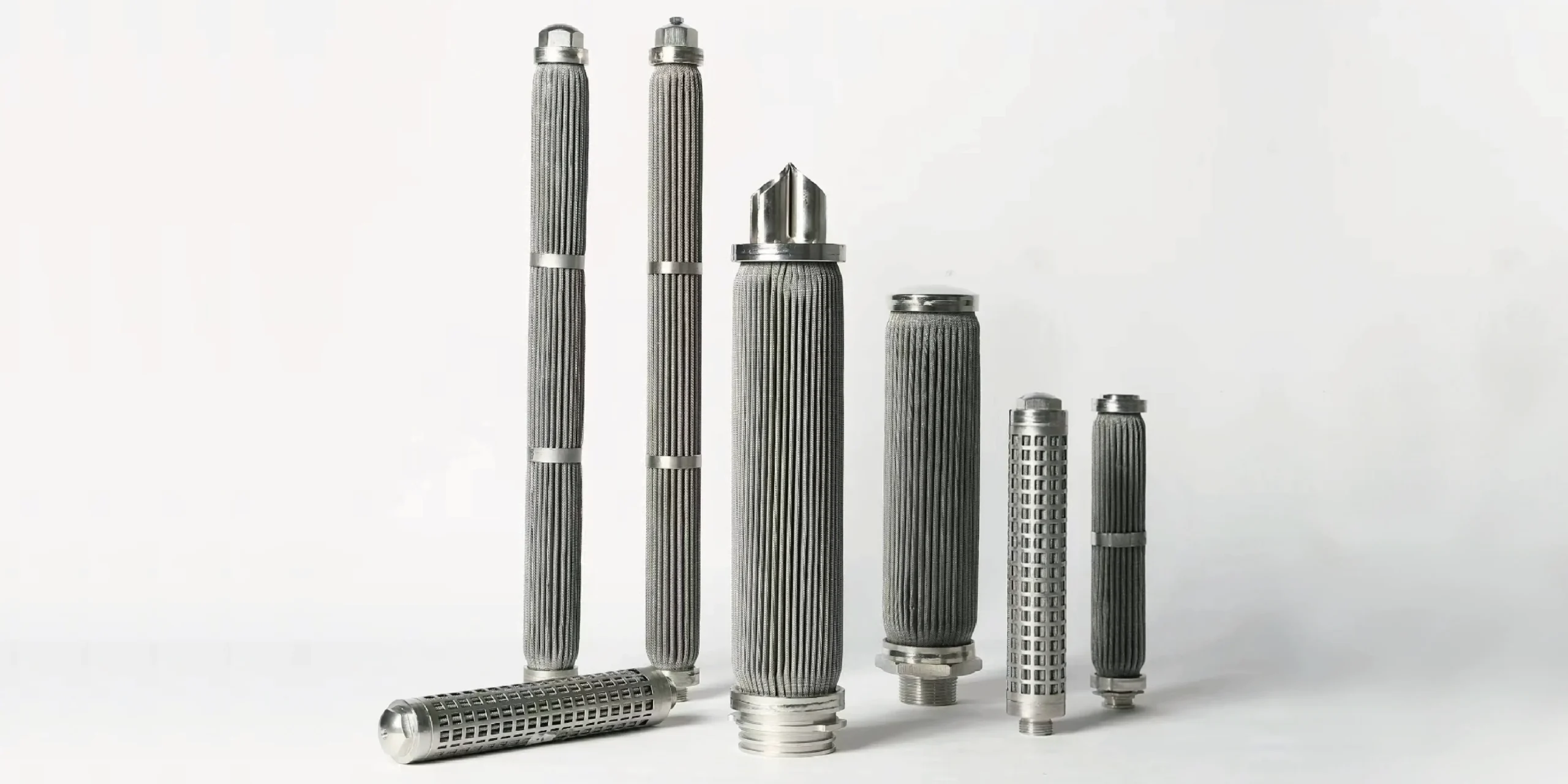
Sintered mesh elements and sintered fiber felt filters are different filtering constructions, not interchangeable pressure-drop ratings. Review retention, area, permeability, supporting parts and cleaning requirements together. A lower clean reading does not establish a longer maintenance interval.
Heating, changing fluid formulation or restricting startup flow are process decisions requiring approval and compatibility checks. Extra media area cannot correct a restricted housing outlet, an incorrectly seated cartridge or an unsuitable seal. Use the industrial cartridge-sizing guide to connect the condition-matched curve with area, element count and physical fit.
What to Confirm Before RFQ
Send fluid properties and paired operating measurements, not just “high pressure drop.” Include:
- Fluid identity, composition, concentration and relevant rheology.
- Viscosity values with units, temperature and measurement conditions.
- Density where conversion or the curve correction requires it.
- Actual flow and fluid temperature at startup, normal duty and relevant peaks.
- Inlet/outlet pressures, measurement locations and whether the reading covers the element or assembly.
- Current clean baseline, trend history, service interval and cleaning history.
- Required retention/rating basis, contaminant characteristics and selected medium.
- Housing drawing, cartridge count, active/overall dimensions, interfaces and flow direction.
- Approved pressure budgets, assembly limits and existing indicator/bypass specifications where applicable.
- Seal compatibility, cleaning conditions, quantity and required documentation.
For a replacement, provide the old part number, drawing, sample or clear photographs. Ask the supplier to state the curve's reference fluid and correction range, which hardware losses it includes and what remains to be qualified. Do not treat burst or collapse-test values as maintenance thresholds.
How SINFT Can Help
SINFT can review drawings, samples, housing dimensions and process conditions for custom metal elements and replacement matching. A useful enquiry combines the viscosity-temperature information with actual flow, retention and the installation drawing.
The manufacturing review can address pleated media, sintered mesh or fiber felt, active length, diameter, end connections and supporting structure. Condition-specific performance must be confirmed for the offered assembly; no universal viscosity limit or pressure-drop curve is implied by the product family alone.
Use the custom filter manufacturing service for non-standard construction or old-sample matching. Send the fluid data and housing drawing with the startup and normal-duty measurements. Plant control settings and overall equipment approval remain with the responsible equipment/process team.
Frequently Asked Questions
Does doubling viscosity double filter pressure drop?
For the same clean medium at the same flow, an approved linear viscous-flow model may predict approximately twice the element pressure drop when dynamic viscosity doubles. That does not establish twice the complete assembly loss. Housing passages, changing flow, loading and nonlinear behavior can alter the result. Use the offered curve's correction method and confirm that the operating range remains within its applicability.
Can a cold-start alarm occur with a clean element?
Yes. More viscous cold oil can produce enough resistance to activate an indicator even without new contamination. However, a startup alarm alone cannot establish cleanliness or safe operation. Record actual flow, temperature and differential pressure, check the clean baseline and follow approved startup procedures. Do not suppress the signal or raise its threshold without the responsible equipment team's review and approval.
Can I use cSt directly in a cP correction?
No. cSt expresses kinematic viscosity, whereas cP expresses dynamic viscosity. With density in g/cm³ at the same temperature, multiply the cSt value by density to obtain cP. Alternatively, follow a supplier method that explicitly uses kinematic viscosity and specific gravity. Do not mix those two approaches or add a second density correction when the method already accounts for it.
Does lower pressure after warmup prove the filter is not clogged?
No. Warming can reduce viscosity-related resistance while accumulated contamination remains. Actual flow may also change, and an assembly bypass or leakage path can change the reading. Compare the element with a clean baseline at matched fluid properties and flow. Interpret that evidence with maintenance history, instrument checks and approved service criteria rather than using one falling pressure reading as proof.
Will choosing a coarser filter solve high-viscosity pressure drop?
A coarser medium may change resistance, but it can also fail the required separation target. Do not change the rating merely to reduce a gauge reading. Review usable area, construction, flow conditions and housing restrictions while preserving retention requirements. Any proposed alternative needs condition-matched performance information, compatibility checks and approval for the downstream cleanliness or product-quality requirement it must satisfy.
Can oil viscosity corrections be used for polymer melt filters?
Not automatically. Polymer melts can have shear-dependent rheology, so a single viscosity value or an oil-based linear correction may not describe their flow through a filter. Obtain data for the polymer grade, temperature and relevant processing conditions. Review flow distribution, media support and cleaning requirements with the equipment and element suppliers instead of transferring a hydraulic-oil calculation to melt service.
Final Thoughts
Treat viscosity as part of the operating condition, not as an explanation that overrides an alarm. Pair differential pressure with actual flow, temperature and fluid data, then compare against an appropriate clean baseline. For a new or replacement metal element, retain the separation target and submit those conditions with the housing drawing. That makes the next review about a defined duty rather than an unexplained pressure reading.