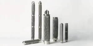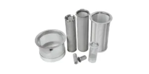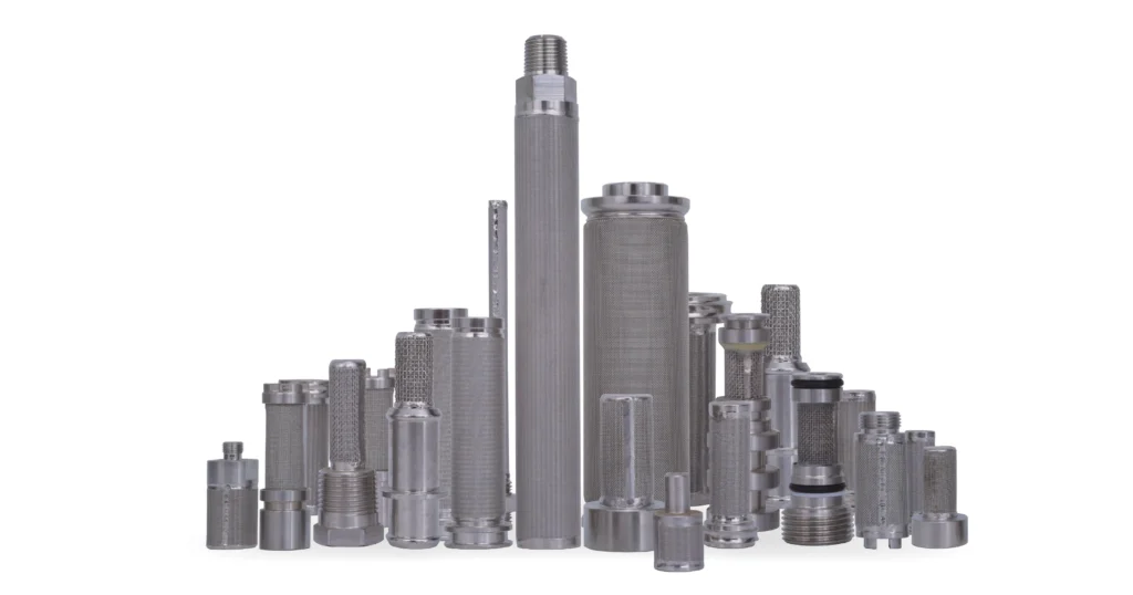
Two replacement screens have the same hole size, but their drawings show different hole spacing. Another quotation lists “40% open area” without saying whether that excludes the welded seam and support. Are these equivalent designs? Filter open area calculation helps answer the geometry question—but only if the opening pattern and reference area are defined. It does not, by itself, establish filtration efficiency, pressure drop or an acceptable operating flow.
Direct Answer: How Do You Calculate Filter Open Area?
Open area percentage equals projected opening area divided by the stated reference area, multiplied by 100. Use a formula appropriate to the pattern: square woven mesh, round-hole perforated plate and continuous-slot wedge wire have different repeating geometries. Then account for inactive margins and assembly obstructions. Keep the resulting open area separate from media surface area, three-dimensional porosity and validated flow capacity.
For purchasing, always ask: “Open area of which layer or assembly, measured over which area?” Without that definition, two percentages can describe different things even when both calculations are mathematically correct.
Define the Area Before Choosing a Formula
Start with a drawing and identify the surface through which filtration is intended to occur. For a flat panel, use the appropriate projected face. For a cylindrical screen wall, an unwrapped developed area can be used for a defined geometric estimate. Do not mix that area with the pipe cross-section or an unrelated outside envelope.
Three quantities should remain separate:
- Gross pattern open area: the fraction open within an ideal repeating pattern, before borders or supports.
- Active patterned area: the portion of the component actually carrying that pattern, excluding solid margins or sealed regions.
- Net geometric opening area: projected openings that remain available after identified assembly obstructions are considered.
“Effective area” is sometimes used differently by suppliers. Define it in your specification rather than assuming it means the last quantity above. It may refer to usable media surface rather than the sum of visible openings.
Hole size sets one dimension of the opening. Pitch, wire width, arrangement and inactive regions determine how often those openings repeat and how much of the component is open. A finer pitch can increase open area for a fixed hole diameter, but it also changes the remaining metal ligament. That is a geometry change requiring structural review—not a free increase in capacity.
Square Woven Wire Mesh: Opening and Wire Diameter
For an ideal square-opening mesh with equal wire diameter in both directions, let a be the clear opening and d the wire diameter. The repeating pitch is a + d. One cell has opening area a² and total projected area (a + d)²:
Open area (%) = [a ÷ (a + d)]² × 100
If mesh count M is stated per inch and wire diameter d is in inches, the equivalent expression is [1 − M × d]² × 100, within this square-mesh convention. Do not combine mesh per inch with millimetres without converting units. Screen Technology Group publishes the mesh-count form of this relationship. Square Mesh Open Area Formula
Here is an independent hypothetical example, not a SINFT product specification. With a 0.50 mm clear opening:
- A 0.25 mm wire gives [0.50 ÷ 0.75]² × 100 = 44.44%.
- A 0.40 mm wire gives [0.50 ÷ 0.90]² × 100 = 30.86%.
The openings are the same size, but the projected opening fractions differ substantially. That does not prove either finished screen has a particular pressure drop or strength. It shows why “same opening” is insufficient for a replacement drawing.
For a genuinely rectangular-opening mesh, calculate the two directions separately: [aₓ ÷ (aₓ + dₓ)] × [aᵧ ÷ (aᵧ + dᵧ)] × 100. Each denominator must describe the actual corresponding pitch. Do not apply the square-opening shortcut to Dutch weave, irregular apertures or a bonded multilayer pack without establishing that the assumed geometry applies.
Perforated Plate: Diameter, Pitch and Arrangement
For round holes, define D as hole diameter and P as the nearest-neighbor centre-to-centre pitch. Pitch is not the clear metal bridge between hole edges. For two adjacent equal round holes along the pitch direction, that bridge is P − D.
With equal pitch in two perpendicular directions, one straight-pattern cell has area P². With a 60° staggered triangular lattice and equal nearest-neighbor pitch, the cell area is √3P²/2. Dividing the round opening area πD²/4 by those cells gives:
| Ideal pattern | Open area formula (%) | Hypothetical D = 3 mm, P = 5 mm |
|---|---|---|
| Round holes, straight square arrangement | (π/4) × (D/P)² × 100 | 28.27% |
| Round holes, 60° staggered arrangement | [π/(2√3)] × (D/P)² × 100 | 32.65% |
| Square holes on equal orthogonal pitch | (S/P)² × 100, S = clear side | Use the actual square-hole dimensions |
These are pattern-only calculations; edges, incomplete holes, seams and supporting structure are not included. The round-hole forms correspond to the approximately 78.54 and 90.69 coefficients published by McNICHOLS. Our numerical example uses independent metric dimensions. McNICHOLS: Perforated Metal Open Area
The same 3 mm holes yield different open fractions because the layouts differ. If the drawing merely says “staggered” without specifying the angle and pitch convention, obtain clarification. A 45° layout, unequal row spacing or a proprietary pattern should not be forced into the 60° formula.
Plate thickness is absent from the projected-area formula, but that does not make it irrelevant. Thickness, edge condition and opening geometry influence the passage through the plate and its mechanical behavior. A geometric percentage cannot replace a review of actual resistance, burrs, corrosion allowance or differential-pressure strength.
Wedge Wire: Slot Width and Surface Wire Width
For an ideal continuous-slot surface, let s be the clear slot width and w the wire face width at the filtration surface. Over a repeating pitch s + w:
Gross slot open area (%) = s ÷ (s + w) × 100
This is a geometric unit-cell expression, before support-rod and end-region deductions. Use the surface face width—not the profile height, downstream width or support-rod size. Hendrick's handbook distinguishes slot opening, wire profile and support spacing, which are separate drawing inputs. Hendrick: Profile Bar and Wedge Wire Handbook
For another hypothetical example, a 0.20 mm slot with a 1.00 mm face gives 0.20 ÷ 1.20 × 100 = 16.67%. Keeping the slot at 0.20 mm while increasing face width to 1.50 mm gives 11.76%. A quotation that states only the slot width therefore leaves the geometric open area unresolved.
The finished screen also has supports and joints. Review their projected obstruction and the actual construction rather than treating the gross slot result as the net assembly opening. For cylindrical or spirally wound designs, confirm the stated dimensions and area convention with the manufacturer; the flat repeating-strip formula is only an idealized starting point.
From Pattern Percentage to Net Opening Area
Multiply a compatible open-area fraction by the active patterned area, not automatically by the full element envelope. For a cylindrical wall estimate:
Active developed wall area = π × reference diameter × active length
Choose the reference diameter for the filtration surface being evaluated. Include an end face separately only if it actually provides filtration and has its own defined construction. A solid bottom does not become open area just because the element resembles a basket.
Consider a fictional geometric example, not a design recommendation. A cylindrical wall is evaluated at a 100 mm reference diameter with 200 mm of active length. Its pattern is 40% open. A separate, non-overlapping seam/support deduction is assumed to block 10% of the otherwise available openings:
| Calculation step | Result |
|---|---|
| Active wall area: π × 100 × 200 | 62,831.85 mm² |
| Pattern openings: active wall area × 0.40 | 25,132.74 mm² |
| Net opening estimate: pattern openings × 0.90 | 22,619.47 mm², or 0.02262 m² |
| Flow of 6 m³/h expressed in m³/s | 0.001667 m³/s |
| Average velocity through the estimated net openings: Q/A | Approximately 0.0737 m/s |
The last line is an average continuity calculation, not a recommended velocity limit or a pressure-drop prediction. Local flow can be uneven, and the complete assembly can contain additional restrictions. A fine liner behind this support would require its own assessment; the example is not a method for bypassing that finer layer.
The assumed 10% deduction is deliberately simple. On a real drawing, calculate the union of blocked projected regions so overlapping seams and support footprints are not subtracted twice. Also verify that a supplier's stated net percentage has not already deducted those features before applying another reduction.
For a finite panel with irregular borders, counting the actual full and partial openings or measuring the CAD opening area may be more reliable than multiplying an infinite-pattern fraction by the outer rectangle. Record the chosen method and revision with the result.
Why Multilayer Filters Need a Different Review
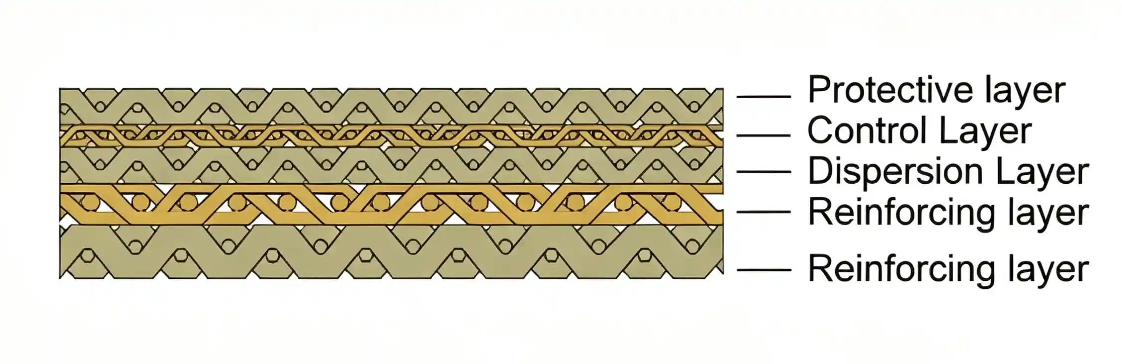
A multilayer sintered mesh element is not simply a single square screen. Layer arrangement, offsets, contact regions and three-dimensional flow paths matter. Multiplying layer percentages assumes a specific overlap model; taking the smallest percentage ignores other restrictions. Neither is a general method for establishing finished-element permeability or usable flow.
For sintered mesh filter elements, identify the control medium, supports and complete construction. Use applicable flow/permeability and retention evidence for the finished design. Do not turn a photographed surface opening into a filtration-efficiency rating.
The same distinction applies to a basket with a perforated support and a fine mesh liner. The support's 40% opening fraction does not mean the fine medium is also 40% open. Inspect the two components and their interaction. Our surface versus depth filtration guide explains why projected openings are particularly unsuitable for describing a depth-type medium's internal structure.
Open Area Is Not a Flow Rating
A larger net opening area can reduce average opening velocity at the same flow, but the percentage alone cannot establish pressure loss. Required inputs also include fluid properties, thickness, media structure, flow direction, housing passages, support and loading condition. Use our filter pressure drop versus flow rate guide to separate the resistance question from the geometry calculation.
Likewise, an opening-area-to-pipe-area ratio is a geometric comparison, not a universal acceptance criterion. Pipe area uses the actual internal diameter: π × ID²/4. State whether the numerator is gross screen face area, net projected opening area or another agreed quantity. Do not apply a supplier's ratio unless both the area definitions and the application are compatible.
The filtration opening must also remain appropriate. Increasing a slot width to achieve a larger percentage changes the particle-size control. For size terminology, refer to the industrial filter micron rating chart. Keep removal performance, opening geometry and allowable pressure loss as separate requirements that must all be satisfied.
Apply the Calculation to the Product You Are Buying
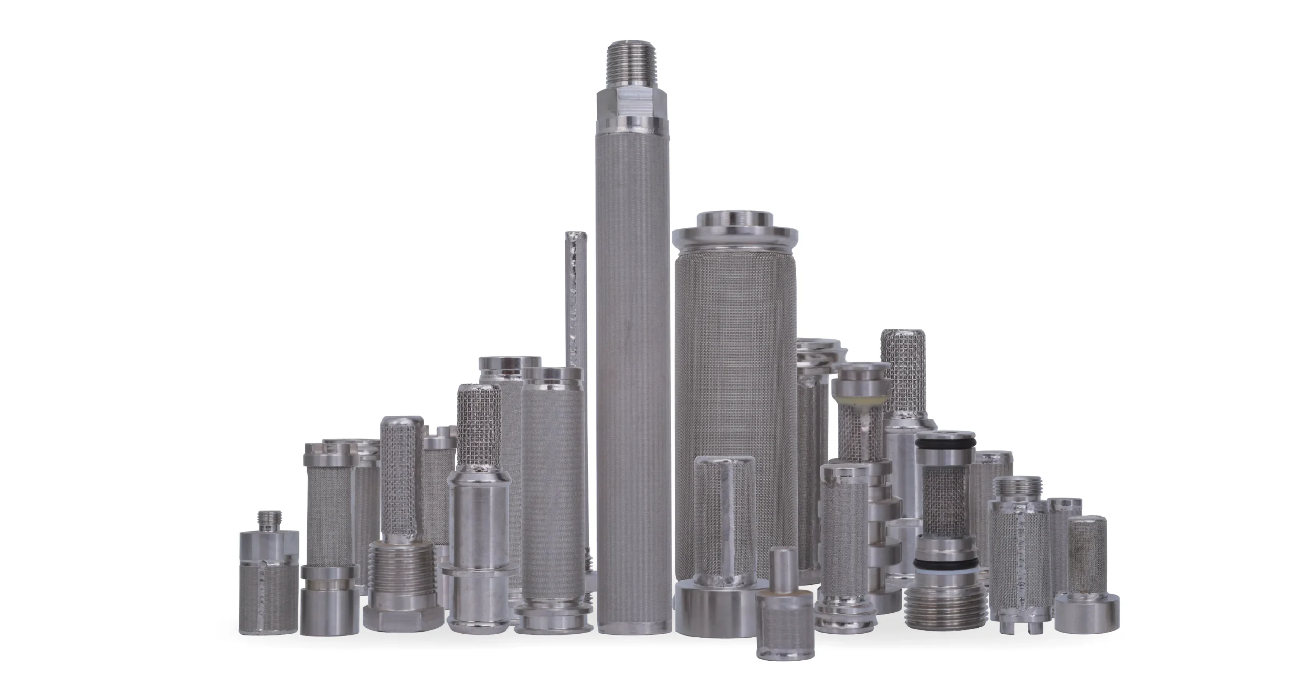
For basket filters and strainers, obtain the active wall and bottom dimensions, pattern, liner, seam, rim and support arrangement. A replacement with the same overall length can have less active perforated length because of different solid margins. Review those differences before accepting the substitution.
For wedge wire screens, specify slot width, surface wire profile, supports, flow orientation and cleaning duty. Do not select the highest gross opening percentage without checking the finished screen's mechanical and maintenance requirements. More geometric opening is not automatically a better supported structure.
In water treatment applications, distinguish clean-screen geometry from solids loading and cleaning behavior. No single blockage allowance fits every feed. In hydraulic applications, especially with fine multilayer metal media, opening calculations are only a drawing check; the required removal performance and relevant operating evidence remain essential.
SINFT's custom filter manufacturing service can review drawings, housing dimensions and replacement requirements. Confirm available verification and documents for the proposed construction. This article does not assign a universal SINFT open-area target, permissible velocity or pressure-drop guarantee.
What to Confirm Before RFQ
Provide the drawing and ask the supplier to state the calculation basis explicitly:
- Opening shape, clear dimensions, wire diameter or surface profile width, and tolerances.
- Centre pitch, row spacing, pattern angle and the units used throughout.
- Active filtration regions, solid borders, weld seam, supports and any filtering end faces.
- Whether the quoted percentage is gross pattern, component net or assembled net open area.
- Each layer's construction, including liners, supports and flow direction.
- Flow, fluid, viscosity, temperature, allowable pressure drop and loading/cleaning conditions.
- Material, thickness, connection, seals, dimensional references and structural requirements.
- Required inspection records and how deviations or substitutions will be approved.
An effective drawing note is:
Identify the reference surface and active dimensions used for the open-area calculation. State the pattern formula and deductions for inactive or blocked regions. Report net geometric opening area separately from media area and flow-performance evidence. Obtain approval before changing opening dimensions, pitch, profile or support construction.
If the drawing is incomplete, flag the missing inputs rather than inserting a favorable default percentage. Send SINFT the drawing, sample details and operating conditions so geometry and duty can be reviewed together.
Frequently Asked Questions
Is open area the same as filtration area?
No. Open area usually describes the projected fraction or sum of openings, while filtration area may describe the usable medium surface. A pleated medium can have substantial surface area without an equivalent projected opening calculation. Ask the supplier to define both terms and their reference surfaces. Do not compare numbers that use different area conventions as though they represent the same property.
Can I calculate open area from hole size alone?
No. You also need spacing and arrangement for perforated plate, wire diameter for square woven mesh, or surface wire width for a continuous-slot screen. Finished-component deductions may also be required. The same hole or slot size can therefore produce different opening percentages. Obtain the missing drawing dimensions before calculating rather than selecting a generic percentage from an unrelated product.
Is pitch the gap between adjacent holes?
Normally pitch means the centre-to-centre repeat distance, not the clear metal bridge between hole edges. For adjacent equal round holes along that direction, the bridge is pitch minus diameter. Confirm the drawing convention, particularly for staggered or unequal-spacing patterns. Using the edge gap as centre pitch can produce a seriously incorrect result, even when the arithmetic is otherwise correct.
Can I multiply the open percentages of several mesh layers?
Not as a general finished-filter calculation. That multiplication assumes an overlap model that may not describe the actual bonded geometry or three-dimensional flow paths. It also does not establish permeability, filtration efficiency or pressure loss. Identify each layer and use appropriate finished-element evidence. A control layer's projected openings alone cannot characterize the full supported sintered assembly.
Does higher open area always mean lower pressure drop?
Not across different constructions. At a fixed flow, greater net opening area lowers the calculated average opening velocity, but thickness, media geometry, viscosity, supports and housing restrictions also influence resistance. Compare the complete assemblies under relevant conditions. Do not use a geometric percentage by itself to guarantee pressure drop or to justify operating above approved equipment limits.
Should I subtract welds and supports from the calculated area?
Yes, when determining an assembled net geometric opening area and when those features obstruct otherwise available openings. Identify their projected footprints and avoid counting overlapping blocked regions twice. Check whether the supplier's quoted net value already includes them. Solid borders should be excluded consistently, and the reference area and deduction method should be recorded with the drawing revision.
Can open area predict when the filter will need cleaning?
Not on its own. Cleaning intervals depend on incoming contamination, deposit behavior, operating conditions and the approved maintenance endpoint. A clean geometric calculation does not describe a loaded screen's resistance or retained contamination. Use appropriate operating records and application validation. Treat any assumed blockage fraction as a stated scenario, not as a universal cleaning limit or service-life prediction.
What should I send for a replacement screen quotation?
Send overall and active dimensions, the opening pattern, hole or slot size, pitch, wire/profile dimensions, material, supports and connection details. Include flow direction, fluid conditions, cleaning method and allowable operating limits. Existing drawings or samples help resolve ambiguous geometry. Ask for the reported open-area basis separately from retention and flow evidence so the proposed replacement can be evaluated consistently.
Final Thoughts
Hole size alone cannot define a filter's open area. Choose the correct pattern formula, use compatible dimensions and subtract inactive or obstructed regions on a clearly stated basis. Then check removal performance, mechanical suitability and flow separately. For a replacement or custom element, share the drawing and operating requirements with SINFT so the quotation reflects the complete assembly rather than an isolated percentage.