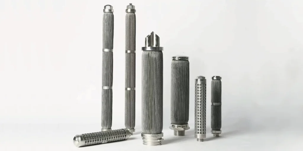
A replacement cartridge can match the old element’s diameter, length and micron rating yet behave differently after installation. The missing detail may be the flow path: which side receives dirty fluid, which side delivers filtrate, and which structure supports the medium under differential pressure. Before approving a replacement or adding backwashing, check how flow direction affects filter element performance across the complete assembly.
Direct Answer: How Flow Direction Affects Filter Element Performance
Flow direction determines which face receives contaminants, how differential pressure loads the medium and its supports, and where released solids travel during cleaning. In cylindrical elements, outside-in filtration generally loads the assembly inward; inside-out filtration loads it outward. The permissible load depends on the finished element, including its support tube, cage, seams, end caps and mounting.
Neither direction is universally better. A suitably designed element can work in either arrangement, but an element approved for one direction is not automatically approved for the other. Reversing a dirty filter for continuous operation also changes the clean and dirty sides and can carry retained contamination downstream. Treat normal filtration and short reverse-cleaning cycles as separate operating conditions.
Inside-Out vs Outside-In: Trace the Actual Flow Path
Define direction relative to the filtering wall, not the pipe connection or the position of the open end. A top inlet can feed either the element bore or the space around it. The housing passages, tubesheet, seals and end configuration determine where the fluid goes next.
| Check | Outside-in filtration | Inside-out filtration |
|---|---|---|
| Dirty fluid starts | Outside the filtering wall | Inside the element bore |
| Flow crosses the wall | Toward the bore | Toward the exterior |
| Filtrate is collected | In the bore or connected outlet passage | In the surrounding housing space |
| Typical surface deposits | On the external upstream face | On the internal upstream face |
| Differential loading tendency | Inward loading | Outward loading |
| Structure to review | Inner core and the complete load path | Outer restraint and the complete load path |
| Reverse cleaning, if approved | From the clean bore toward the dirty exterior | From the clean exterior toward the dirty bore |
These are schematic relationships, not instructions for changing an existing installation. The medium may be multilayered or depth-loading, and the finished assembly may use supports on both sides. Document the approved direction on the drawing and identify dirty-side and clean-side connections on the housing schematic.
For an old element with no readable identification, photograph both ends, the internal core, the outer surface, the sealing seat and the housing passages. Deposits can provide a clue to the upstream face, but they do not establish a manufacturer’s approved direction or pressure limit.
Structural Support: Inward and Outward Loads Are Different
The same differential-pressure magnitude can produce a different failure mode when the direction reverses. In an outside-in assembly, the medium tends to move toward its internal support. A correctly designed core helps resist that movement. If the core, unsupported span or attachment is inadequate, deformation can restrict passages or damage the filtering wall.
Inside-out operation places a different demand on the element. The medium and attachments must withstand outward loading. Depending on construction, an outer cage, bonded layers or another restraint may provide support. Welds and end-cap connections also belong to the load path. A visible protective mesh should not be assumed to provide a verified outward pressure rating.
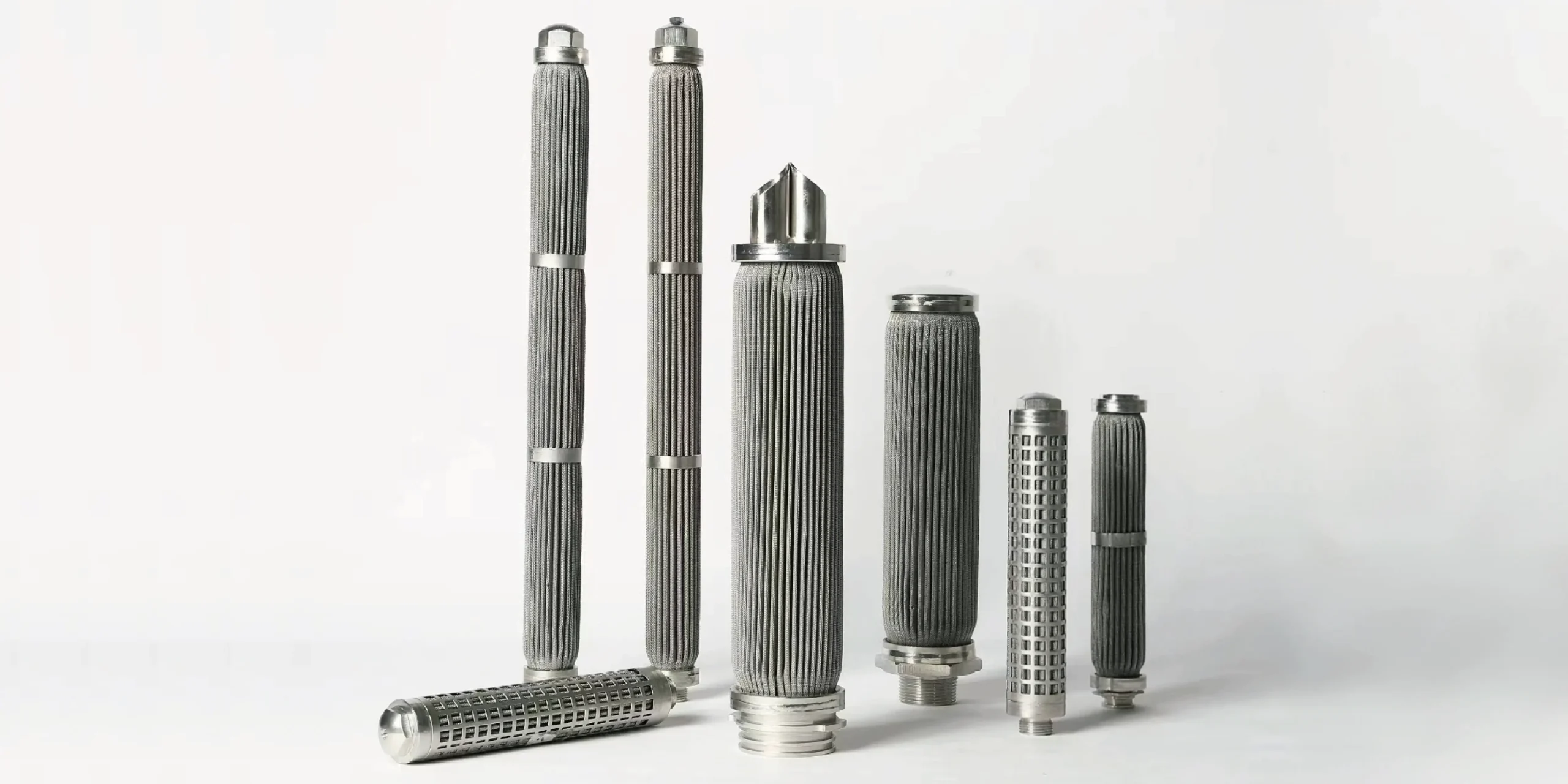
Pleats add another consideration. Under load, folds can deflect, touch adjacent folds or shift against a support. That movement can reduce usable flow passages before obvious rupture occurs. Review pleat spacing, support contact and attachment details together when specifying pleated filter cartridges.
Ask for separate forward and reverse allowable differential pressures at the relevant temperature. Also establish whether a quoted value is an operating limit, a proof-test condition or a destructive test result. The filter element collapse-pressure guide explains why those values cannot be treated as interchangeable.
System pressure and element differential pressure are separate quantities. A housing may withstand high line pressure while an element has a much lower permissible pressure difference across its wall. Direction approval must cover the element, seals and retention arrangement as well as the vessel.
Pressure Drop: What Changes When Flow Reverses?
Reversal does not automatically increase or decrease clean pressure drop. For a clean, rigid, symmetric porous medium carrying a liquid in a regime where linear resistance is a reasonable approximation, changing direction alone may give similar medium resistance. Real cartridges also contain supports, drainage layers, end passages and nonuniform flow paths that may behave differently.
Several effects deserve separate checks:
- Asymmetric construction: Layer order, entrance geometry and supporting passages can influence how fluid reaches and leaves the control layer.
- Flow distribution: The bore, annular space, connection and housing can distribute flow unevenly along the element.
- Deformation: Pleat movement or support deflection can alter available passages under load.
- Contamination: The deposit pattern and cake resistance evolve on the new upstream side.
- Operating conditions: Flow rate, viscosity and temperature can change during startup or cleaning, making a simple directional comparison misleading.
For incompressible flow through an ideal cylindrical wall, the available cylindrical area changes with radius. The superficial radial velocity therefore changes across the wall even when total flow is constant. Pleated geometry is more complex, so the inner and outer diameters alone do not establish a cartridge’s performance advantage.
Compare pressure drop at the same fluid, temperature, viscosity, flow rate and loading condition. Record pressure-tap locations: a measurement across the whole housing can include connection and housing losses as well as the element. A directional claim based on different test conditions is not a reliable purchasing comparison. Use the filter pressure-drop and flow-rate guide for the broader sizing relationship.
Particle Retention and Loading: The Upstream Face Matters
Changing direction does not simply change the stated micron rating, but it can change how particles encounter and load the assembly. An opening remains an opening only while the structure retains its geometry and fluid passes through the intended path. Distortion, a damaged seam or a bypassing seal can compromise the result regardless of the label.
In surface filtration, particles tend to collect at or near the upstream filtering face. Their size, shape, adhesion and compressibility influence cake formation and removal. Changing the upstream face can expose a supporting layer before the fine control layer or place deposits where access for cleaning is poor.
Depth media require additional care. Some constructions use a deliberate pore or density arrangement through their thickness. Reverse operation can change the loading pattern and service behavior. Even where the medium itself is directionally similar, its protective layers and assembled supports may not be. Do not infer bidirectional approval from a random fiber appearance.
An element’s retention claim should apply to the intended direction and relevant test conditions. If both directions are required for normal filtration, include that requirement in the supplier’s validation scope. Short reverse cleaning is a different requirement from validated particle retention during continuous reverse filtration.
Media-Specific Flow-Direction Checks
Multilayer Sintered Mesh
Confirm the fine control layer’s position and the support arrangement in the finished element. A five-layer mesh can contain protective, control, dispersion and reinforcing layers with different functions. Their presence does not make every cylindrical assembly equally suitable for inward and outward pressure loading.
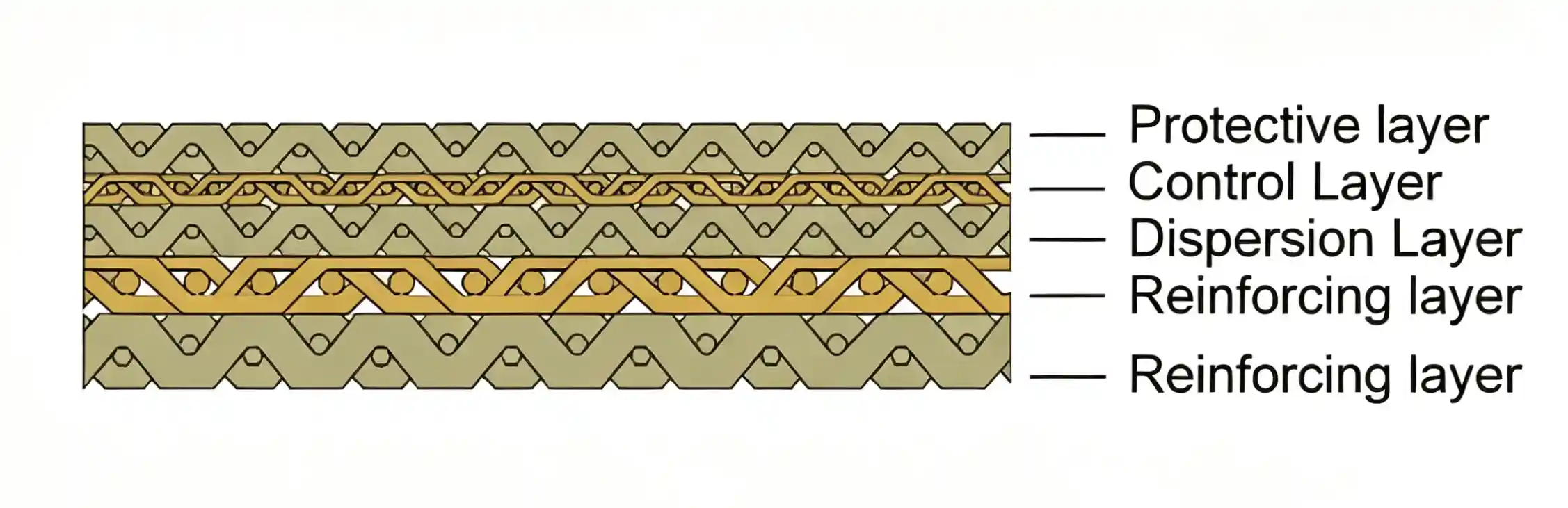
For sintered mesh filter elements, ask how the sheet is oriented when formed, how the longitudinal seam is joined, and how the end fittings transfer load. Review forward filtration and reverse-cleaning limits for the actual diameter and length. A material-sheet rating is not automatically the assembled element’s rating.
Metal Fiber Felt and Pleated Media
Metal fiber felt offers a porous depth structure, but deposited material can remain within that structure after surface deposits are removed. Increasing reverse-cleaning intensity does not guarantee recovery and may exceed the assembly’s limits. Confirm the selected grade, protection meshes, supports and approved cleaning method.
For pleated constructions, inspect both sides of the pleat pack and the end attachments. A guard can protect the surface during handling without establishing a reverse-pressure capability. Require the supplier to identify its structural function and the limits it supports.
Wedge Wire and Slotted Screens
Specify the filtering face and slot orientation, not just “wedge wire.” Profile-wire construction can be arranged for outside-in or inside-out duty. The relationship between the narrow slot entrance, wider passage and support rods must match the intended use.
Johnson Screens’ industrial screen brochure presents different cylindrical constructions for these directions, including arrangements intended to provide an accessible surface for internal or external cleaning. This supports an important design check: geometry and cleaning access belong in the same specification.
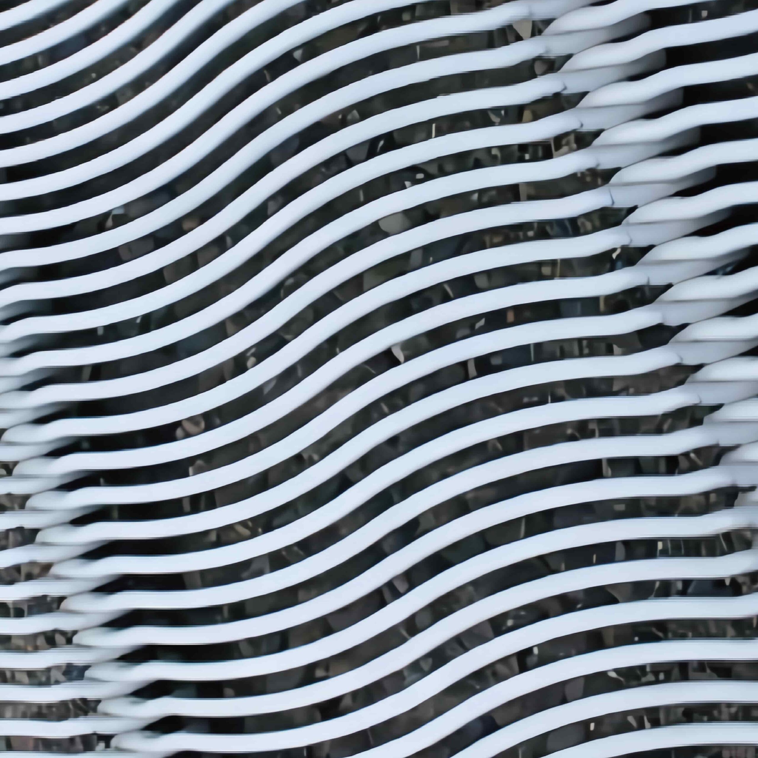
For wedge wire filters, identify the dirty-side surface, support-rod location, scraper contact if used, and whether reverse flow occurs only during cleaning. A screen manufactured for one service direction should not be repurposed by changing the housing connections alone.
Backwashing: Reverse Flow Needs Its Own Specification
Backwashing temporarily sends cleaning fluid from the clean side toward the fouled side, with an exit path for the released material. It does not mean that the element can continuously filter in the reverse direction, or that its reverse differential limit equals its forward limit.
Pall’s gas-solid separation literature describes reverse-flow removal of a surface cake in a purpose-designed system. The relevant principle is the coordinated sequence of filtration, cake release and solids removal. Its operating performance should not be transferred to a different liquid filter or metal element.
Before approving a backwash cycle, confirm:
- The actual reverse pressure difference across the element, including transients.
- Cleaning-fluid compatibility, temperature, quality and available flow.
- Cycle duration and repetition, and the approved limits for the assembly.
- The drain route and isolation sequence that keep released solids out of the clean outlet.
- End retention and seal behavior under the reversed load.
- The acceptance checks before returning to service.
Supply pressure alone is not the reverse differential across the element. Resistance in valves, passages and drains affects how the cleaning flow is distributed. A strong supply with a restricted outlet may produce an excessive load while removing little contamination.
Retention deserves particular attention. Pall’s Ultipleat High Flow housing literature describes a hold-down arrangement intended to prevent element displacement during reverse flow. That is a product-specific example of why mounting review must accompany media-strength review, not a SINFT design specification.
For backwash filter cartridges, define forward filtration and reverse cleaning on the same drawing. After cleaning, compare pressure drop at equivalent operating conditions and check filtrate quality, leakage and physical condition. Low pressure drop by itself can also result from damage or bypass, so it is not sufficient proof of successful regeneration.
Troubleshooting a Suspected Flow-Direction Problem
Use a flow-path check before changing the operating arrangement. Follow the inlet through the housing to the upstream face, through the medium and into the outlet. Compare that route with the element drawing and the manufacturer’s direction approval.
| Observation | Possible direction-related issue | Other causes to check |
|---|---|---|
| High pressure drop immediately after replacement | Layer orientation, passages or support differ from the approved design | Cold viscous fluid, incorrect rating, trapped gas or blocked passages |
| Inward deformation | Inadequate support for outside-in differential loading | Excessive loading, transient pressure, corrosion or damage |
| Outward bulging or separated attachment | Insufficient outward restraint or unapproved reverse loading | Manufacturing defect, temperature exposure or pressure excursion |
| Poor filtrate quality after cleaning | Released solids reached the outlet, or reversal disturbed seals/media | Incorrect isolation sequence, damage or inadequate rinsing |
| Little recovery after backwash | Cleaning flow does not reach or release the deposits effectively | Embedded contaminants, unsuitable chemistry or restricted drain |
These observations are diagnostic leads, not proof of a single cause. Preserve photos, the installed arrangement, pressure trends and the removed element. Avoid attributing every high-pressure-drop event to direction without checking flow, viscosity and contamination.
Application Advice for Replacement and New Equipment
Hydraulic and lubrication systems: Review cold-start viscosity, bypass behavior where present, pressure transients and any return-flow events. An element that fits the housing still needs the approved differential capacity and retention performance. Include the operating sequence, not only nominal line pressure, in a replacement request.
Water treatment and self-cleaning filters: Define the dirty-side surface, cleaning flow route and drain sequence. Match the screen orientation to the intended scraper or reverse-cleaning arrangement. The water-treatment application page is the relevant starting point for selecting a metal filtration construction.
Polymer and viscous process fluids: Confirm temperature and viscosity during normal operation and startup, along with pleat support and housing distribution. Direction changes should be evaluated with the process conditions that determine hydraulic resistance. A low-viscosity bench test cannot establish equivalent performance in a hot or viscous production duty.
Replacing an unidentified element: Keep the old sample, record its installed direction and photograph seals and supports before removal. Use the stainless steel element selection guide to complete the wider specification. Direction is one part of equivalence alongside materials, dimensions, retention and cleaning.
What to Confirm Before RFQ
A useful RFQ includes a flow diagram as well as an element drawing. Mark dirty and clean sides, normal flow, reverse cleaning and the connections used in each mode. If direction approval is unknown, state that explicitly and provide the old sample and housing information.
- Fluid or gas, contaminants, concentration and relevant viscosity conditions.
- Normal, maximum and startup flow with operating temperatures.
- Required retention rating or slot size and its acceptance basis.
- Normal filtration direction and whether either direction is required in service.
- Allowable forward and reverse differential pressure at temperature.
- System pressure, expected transients and cleaning sequence.
- Medium, layer orientation, inner core, outer restraint and attachment requirements.
- OD, ID, length, end connections, sealing seat and retention method.
- Backwash fluid, available flow, cycle duration, frequency and drain conditions.
- Inspection documents and acceptance checks, including any directional testing needed.
Ask suppliers to quote against the same operating modes. A single pressure value with no direction, temperature or test basis leaves a major comparison gap.
How SINFT Can Help
SINFT manufactures metal filtration elements and custom assemblies from drawings, samples and operating requirements. When direction affects the replacement decision, the review should cover the medium, support tube, outer restraint, seams, end fittings and housing interface together.
Use the custom filter manufacturer service for drawing-based or old-sample matching. Submit the flow diagram, element dimensions, fluid conditions and separate filtration and cleaning requirements through the inquiry form. Confirm the finished assembly’s limits and inspection scope before treating it as an equivalent replacement.
Frequently Asked Questions
Is outside-in filtration always better than inside-out?
No. The appropriate direction depends on the housing, medium, support arrangement, contaminant and cleaning method. Outside-in operation creates inward differential loading; inside-out creates outward loading. Each needs a suitable structural load path and clean-side collection route. Compare the complete assemblies at equivalent conditions rather than selecting a direction based on a general claim about pressure drop or dirt capacity.
Can a stainless steel filter element operate in both directions?
Only if the finished assembly is approved for the required modes. Stainless steel material alone does not establish bidirectional capability. The filtering layers, supports, welds, end caps, seals and retention can have different limits under reversed loading. State whether you need continuous filtration in both directions or a short reverse-cleaning cycle, and request the relevant operating limits and validation.
Does reversing flow change the micron rating?
The marked rating does not automatically change, but its performance basis may apply to a specified direction. Layer orientation, loading pattern, deformation and bypass can influence actual retention. A filter’s pore size or nominal label is not proof of equivalent directional performance. If bidirectional filtration is required, ask how retention is verified in each direction and under the intended operating conditions.
Why can reverse differential pressure be lower than forward differential pressure?
Reversal changes which parts resist the load and how the filtering medium contacts its support. An inner core that supports inward loading may provide little restraint against outward movement. Outer guards, attachments and seals can also impose different limits. Obtain separate allowable values for the finished assembly at temperature instead of assuming that one differential-pressure figure covers both modes.
Can backwashing damage a metal filter element?
Yes, if reverse pressure, temperature, chemistry or repeated loading exceed its approved conditions. Metal construction does not eliminate the possibility of deformation, seam damage or seal displacement. Effective cleaning also requires suitable contaminants and a route for released solids to leave. Follow the validated cycle and assess pressure-drop recovery, filtrate quality and physical condition before returning the element to normal service.
How do I identify direction when the old element has no arrow?
Trace the housing inlet and outlet passages and compare them with available drawings. Photograph the supports, end connections, sealing seat and deposit locations before cleaning. Deposits may help identify the former upstream side, but do not establish the approved structural limit. Send the old sample and housing information for review when the original specification cannot be recovered.
Final Thoughts
Flow direction belongs in the filter specification alongside retention, dimensions and materials. Identify the dirty and clean sides, verify the structural load path, compare pressure drop under equivalent conditions and define reverse cleaning separately. Before ordering a replacement, provide the flow diagram and drawing so the finished element, its connections and its operating limits can be reviewed as one assembly.