Your filter's differential pressure is rising, but another identical cartridge may not solve the problem. The change could come from retained solids, colder fluid, increased throughput or a replacement that fits the housing without matching the duty. Understanding why industrial filter pressure drop increases starts with the timing: did it rise gradually, appear during startup, or begin immediately after maintenance? Each pattern calls for different evidence before you order the next element.
Direct Answer: Why Industrial Filter Pressure Drop Increases
Industrial filter pressure drop increases when resistance rises, the fluid becomes harder to move, or more flow passes through the available passages. Common causes include contaminant loading, higher viscosity, increased flow, unsuitable element specifications, installation restrictions, trapped gas in liquid service, and physical damage or deposits left after cleaning. A faulty measurement can also create an apparent increase.
Treat these as possibilities, not a diagnosis from one gauge reading. Follow the equipment's approved alarm response first. Where evaluation is permitted, compare readings at matched flow, temperature and fluid conditions, then examine the event history. Do not raise pressure limits, defeat bypass protection or keep operating simply to finish a troubleshooting checklist.
First Confirm What the Instrument Is Measuring
Validate the reading before blaming the element, without delaying any required shutdown or service action. Differential pressure is the difference between pressure at two defined locations during flow. One upstream gauge is not enough when downstream pressure changes.
Record the inlet and outlet readings together, their units and the pressure-tap locations. A measurement spanning a valve or extra piping includes those losses; it does not isolate the filtering medium. A downstream restriction outside both taps can change upstream pressure or the operating point without directly becoming a loss across the filter.
Have qualified personnel check instrument range, calibration, connections and any sensing-line obstruction under the applicable procedure. Emerson's wet-gas measurement note describes how accumulated material in impulse lines can bias or destabilize a DP signal. Its wet-gas context is not a universal explanation for every liquid installation, but it reinforces the need to verify the measurement path.
Before opening a housing, disturbing a connection or inspecting an element, isolate and depressurize the equipment, address stored energy, temperature and chemical hazards, and follow the site's approved maintenance procedure. Never loosen a pressurized fitting as an improvised diagnostic test.
Read the Trend Before Choosing a Remedy
The relationship between pressure loss, process conditions and maintenance events is more useful than an isolated peak. Use the table to choose the next check; none of these patterns proves a cause alone.
| Observed pattern | Causes to investigate | Evidence to collect |
|---|---|---|
| Gradual rise at comparable conditions | Loading, deposits or increasing feed contamination | Matched-condition trend and feed history |
| High at startup, lower during normal operation | Viscosity, filling or startup-flow changes | Temperature, fluid properties and actual flow |
| Peaks with production demand | Higher flow or too little usable area | Peak flow and supplier sizing basis |
| High immediately after element change | Wrong grade, restricted fit, direction or trapped gas | Old/new specifications and installation record |
| High after cleaning | Residual fouling, damage or changed test conditions | Cleaning record and acceptance results |
| Abrupt or erratic change | Process upset, gas, mechanical change or instrument fault | Time-aligned operating and instrument records |
If flow falls as resistance grows, pressure drop may plateau instead of continuing to rise. A sudden decrease also does not prove recovery: reduced flow, bypass operation, a sealing leak or media damage may be involved. Preserve the flow and downstream-quality evidence alongside the pressure trend.

Seven Causes to Check Before Replacing the Element
1. Contaminant Loading or New Deposits
A rising trend at matched conditions makes additional retained material a strong candidate. Solids can obstruct passages or form a surface deposit. Some contamination also enters the depth of the medium, so a relatively clean-looking exterior does not exclude loading.
Compare the current run with previous runs using elapsed time and processed volume. Check whether a tank cleanout, upstream maintenance, new raw-material batch or process upset preceded the change. Keep a suitable deposit sample and photographs when the maintenance procedure allows it.
Distinguish ordinary capture from an upstream problem. Replacing the element may restore flow temporarily while leaving the source of repeated loading untouched. Changing to a coarser grade without confirming downstream requirements can exchange a pressure problem for a contamination problem.
2. Higher Viscosity or a Changed Fluid
Compare viscosity at the actual filtration temperature, not just the fluid name on the purchase order. Cold oil, a formulation change or a different concentration can change resistance without adding dirt. Viscosity and temperature should therefore accompany every baseline comparison.
The HYDAC clogging-indicator discussion explains why cold hydraulic or lubrication fluid can trigger an indication associated with clogging. That principle does not authorize ignoring an alarm or adding thermal lockout to another installation.
Check the approved startup procedure and obtain the fluid's relevant property data. For the detailed relationship and its limits, see how viscosity affects filter pressure drop. Do not assume warming, dilution or a temperature-setpoint change is acceptable for the process.
3. Higher Actual Flow or Uneven Flow Sharing
A filter can show higher pressure loss because it is carrying more flow, even when it remains clean. A production increase, changed operating sequence or unavailable parallel branch may alter the duty seen by the active elements.
Measure actual flow where possible rather than equating pump speed with throughput. In a multi-element housing, confirm the active element count, approved internal arrangement and whether flow paths are obstructed. Equal sharing should not be assumed solely because cartridges have the same outside dimensions.
Compare the complete assembly with the supplier's sizing basis. The pressure-drop versus flow-rate guide explains why the element and housing must be considered together. Do not use increased pump pressure as a substitute for resolving an undersized or restricted assembly.
4. A Replacement That Matches Dimensions but Not Specification
A matching length, diameter and micron label do not establish equivalent hydraulic performance. The replacement may use a different medium, grade, layer stack, pleat geometry, support construction or end opening. Each can affect the available flow path.
Compare the approved old specification with the supplied part identification and drawing revision. Confirm the filtration-rating basis, effective area, media construction, connection details and clean-flow data at the required conditions. A nominal rating and an absolute rating should not be treated as interchangeable labels.
When a new element has a high baseline from the first run, specification review belongs early in the investigation. Do not assume either that every new element is defective or that physical fit proves suitability. Ask what changed between the approved and supplied constructions.
5. Installation, Connection or Flow-Direction Restrictions
An installation change can restrict flow or load the element in an unintended direction. Check the approved housing schematic and element drawing, not just the apparent location of the inlet pipe.
During authorized inspection, review end seating, insertion depth, spacers, adapters, support engagement and seal placement. A displaced seal or misaligned connection may obstruct a passage. Other sealing faults may instead allow bypass and lower the apparent loss, so do not classify every assembly fault as a high-pressure-drop fault.
Confirm the normal filtration direction and any separate reverse-cleaning approval. A protective mesh is not automatically a structural support in both directions. See how flow direction affects filter element performance before specifying an apparently equivalent replacement or changing the cleaning arrangement.
6. Trapped Gas or Incomplete Filling in Liquid Service
Unexpected behavior after draining, refilling or maintenance warrants checking the approved filling and venting process. Trapped gas can interfere with stable liquid flow or pressure transmission. Its symptoms depend on the housing and measurement arrangement; it does not always produce a steady increase in filter DP.
Note when the behavior began and whether flow or readings fluctuate. Review the equipment manual with qualified personnel. Pall's UH211 service instructions provide a model-specific example of controlled filling and bleeding, demonstrating why this task belongs to the actual assembly procedure.
Do not copy another filter's venting sequence or torque values. Never crack open a live connection. This liquid-service check also should not be confused with the normal compressible behavior of a filter deliberately operating on gas.
7. Damage, Deformation or Incomplete Cleaning
A cleaned element can retain resistance, and a damaged element can lose filtration integrity without showing high DP. Residual deposits may remain in pores or inaccessible areas. Deformed pleats, a restricted core or damaged supports can reduce usable passages.
Review the cleaning method, chemistry, temperature and handling history against the approved construction. Examine media, seams, end connections and supports using the specified inspection method. Compare flow or permeability with an accepted baseline; use the applicable integrity check rather than relying on appearance alone.
Do not repeatedly escalate cleaning intensity until the reading falls. Quarantine an element with unresolved damage or failed acceptance checks. The replacement specification should address the confirmed failure mechanism, not merely reproduce the same external dimensions.
When a New or Cleaned Element Still Has High Pressure Drop
Use the first acceptable clean baseline as a reference, not a different fluid or an undocumented historical reading. These comparisons help separate element condition from a system or specification change.
| Situation | Next review | Avoid concluding |
|---|---|---|
| New element, high first-run loss | Match duty, grade, fit, direction and filling | “New means suitable” |
| Cleaned element, same matched-condition loss | Review residue, deformation and acceptance data | “Looks clean means reusable” |
| Known approved replacement, unchanged symptom | Verify measurement boundary and process changes | “Another identical replacement will fix it” |
| Lower loss but worse downstream quality | Check flow, seals, bypass and media integrity | “Lower DP proves recovery” |
Pall's Principles of Filtration identifies fluid properties, medium, hardware and retained material as relevant to filtration resistance. The practical implication is to review the complete duty rather than reduce every symptom to the micron number. Supplier curves and inspection evidence must still relate to the offered assembly.
Apply the Checks to Your Service
Use the same diagnostic logic, but collect application-specific evidence. A hydraulic-oil baseline cannot simply be applied to water, polymer melt or gas service.
- Hydraulic and lubrication: correlate temperature, actual flow and oil identity with the pressure trend. Include recent maintenance and contamination records. The hydraulic filtration application page provides the relevant element context.
- Polymer melt: record formulation, process temperature and throughput together. Review deposits and cleaning history; apparent viscosity can depend on processing conditions, so a simple liquid correction may be inadequate.
- Water and backwash service: compare the post-cleaning baseline over successive cycles. Review feed solids and the approved cleaning sequence before changing settings or assuming a different cartridge alone will restore performance.
- Gas service: use gas-specific sizing and actual pressure, temperature and flow definitions. The liquid filling discussion and liquid viscosity comparisons do not transfer unchanged.
What to Send Before Requesting a Replacement Quote
Send a troubleshooting record with the drawing or sample. This gives the supplier a basis for reviewing what the replacement needs to match or change.
- Fluid identity, composition and viscosity data with temperature and units.
- Normal and peak actual flow, operating pressure and temperature.
- Paired pressure readings, tap locations and instrument information.
- Clean baseline and the trend leading to the current symptom.
- Existing part number, drawing revision and old/new element photographs.
- Required filtration rating and its nominal/absolute or efficiency basis.
- OD, ID, length, end connection, sealing position and housing drawing.
- Approved flow direction, service limits and cleaning conditions.
- Feed changes, maintenance events, cleaning records and inspection results.
- Required quantity, materials, traceability and inspection documents.
Keep line-pressure ratings separate from allowable element differential pressure. Do not use a structural test rating as a maintenance trigger, and do not ask the supplier to infer critical limits from photographs alone.
How SINFT Can Help Review the Element Specification
SINFT can review metal-element construction and replacement fit against the submitted duty. That review supports component selection; it does not replace the equipment owner's operating approval or a site investigation.
For a compact housing, pleated filter cartridges offer a construction to evaluate when area, medium and connections need matching. Sintered mesh filter elements provide a different multilayer metal structure for duty-specific review. Neither family guarantees a pressure-drop reduction without comparable data.
For systems designed for reverse cleaning, review backwash filter cartridges against the actual cleaning direction, support and assembly limits. Reusability must be confirmed for the specific element and service.
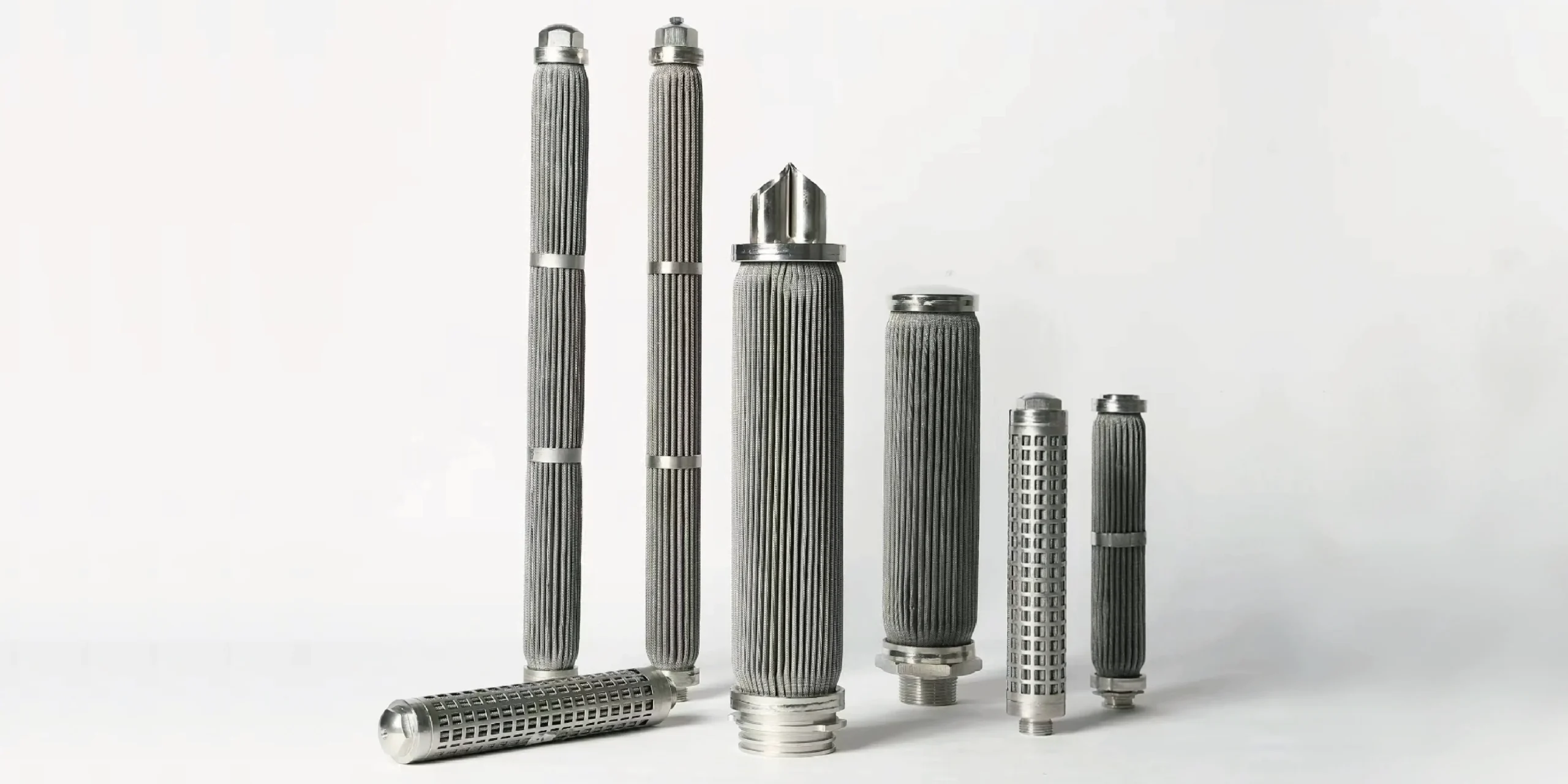
If the old part has incomplete documentation, start with a custom filter replacement review using the drawing, sample and operating record. Send the specification and troubleshooting evidence so the discussion focuses on an identified requirement rather than an unsupported promise of lower pressure drop.
Frequently Asked Questions
Does high differential pressure always mean the filter is clogged?
No. High differential pressure can reflect contamination, higher viscosity, increased flow, restricted installation or a different element specification. An instrument problem can also create an apparent change. Compare the current reading with a verified clean baseline under matched conditions and follow the approved alarm response. Do not use the absence of visible dirt as proof that the medium is unrestricted.
Why does a brand-new filter element have high pressure drop?
A new element may have a different medium, effective area, support structure or connection even when its outside dimensions match. Incorrect seating, incomplete filling or changed operating conditions are other possibilities. Compare the supplied identification and drawing with the approved specification, then verify actual flow and fluid properties. A new part is not automatically an equivalent part for the installed duty.
Can trapped air cause an abnormal filter pressure reading?
In liquid service, trapped gas can affect stable filling, flow or pressure transmission, particularly after draining or maintenance. It does not always cause a steady high differential pressure, so the symptom alone is not diagnostic. Check the assembly's approved filling and venting procedure with qualified personnel. Never loosen a pressurized connection, and do not copy venting instructions from an unrelated model.
Why is pressure drop still high after cleaning a metal filter?
Deposits may remain inside the medium, or cleaning and handling may have damaged pleats, supports or connections. A different test flow, temperature or fluid can also make the comparison misleading. Review the cleaning record, repeat the approved acceptance checks and compare against a matched baseline. A visibly clean surface does not establish restored permeability, filtration integrity or suitability for further service.
Should I choose a coarser micron rating to reduce pressure drop?
Not without confirming the downstream contamination requirement. A coarser grade may change resistance, but it can also change what reaches protected equipment or the process. First review the cause, available area, medium construction and housing restrictions. Any proposed rating change needs an agreed filtration-performance basis and equipment approval, rather than a decision made solely to obtain a lower gauge reading.
When is replacement the appropriate next step?
Replace or quarantine the element when required by the equipment procedure, confirmed damage, failed acceptance checks or an unresolved mismatch that makes continued use unsuitable. A cleanable element may instead qualify for approved cleaning and inspection. The root-cause investigation helps specify the next part, but it must not delay mandatory service action or turn a pressure alarm into permission to continue operating.
Final Thoughts
Start with the measurement and the event history, then compare flow, fluid conditions and element details. The useful question is not simply whether pressure drop is high, but what changed and what evidence supports that conclusion. Follow the approved service limits throughout the investigation. When a replacement is needed, give SINFT the duty, drawing and troubleshooting record so the specification addresses the identified problem rather than repeating an uncertain match.