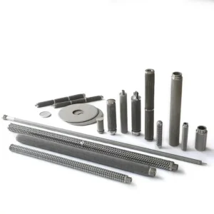
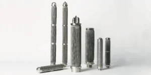
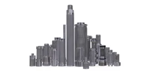
Two sintered mesh cartridges are both marked 10 µm and fit the same housing. At the same flow, one needs more inlet pressure to deliver the same outlet pressure. The grade describes a filtration requirement on a stated basis. The resistance depends on the full path the liquid takes through the laminate, its support, and the cartridge outlet. To compare quotations, ask for clean pressure drop at your duty conditions.
What Determines Sintered Mesh Filter Pressure Drop?
At a given flow and viscosity, clean pressure drop depends on the permeability and thickness of the mesh laminate, the area available to carry flow, and the restrictions in the element and housing. Two 10 µm filters can use different layer combinations or have different effective areas. They can also direct flow through different support tubes or outlet fittings.
Start by confirming that both quotes define 10 µm on a comparable basis. Then compare their curves at the same flow, fluid, and test boundary. Keep the allowable pressure drop for normal operation separate from the maximum differential the element can withstand. See the sintered mesh micron rating guide.
Follow the Flow Through the Laminate and Support
The fine control layer establishes the intended filtration path. Coarser layers can protect the control layer, distribute flow, and provide support. The liquid still passes through the assembly of layers. Weave, wire dimensions, and the thickness and openness of the stack can all affect its resistance. The layer count alone leaves those details unspecified. Porvair shows an example of multilayer mesh made with different layer combinations and optional perforated plate support. Sinterflo MC construction overview.
Next follow the liquid through the support. A perforated core can limit where liquid leaves the mesh and how it collects inside the element. Its open area, the spacing between openings, and the clearance for drainage behind the laminate influence the flow path. An outlet fitting with a narrower passage can add another loss. Request the proposed cross-section if both suppliers list the same outside diameter and length but their curves differ. Five-layer sintered wire mesh guide.
Compare the Area Available to Carry Flow
A cartridge's outside surface includes regions near the end fittings or joints that may contribute little or no filtration area. Supports can also restrict access to parts of the mesh. Ask how the supplier calculated effective area and whether the value applies to the assembled element. Use area to explain differences between designs, then check the finished element curve to assess their impact at your operating point.
Suppose two clean elements carry 30 L/min. If their effective areas are 0.15 m² and 0.10 m², the respective average flows per unit area are 200 and 300 L/min per m². The smaller element carries 50% more flow per unit area. These values are hypothetical. The example gives a reason to expect different media losses for comparable laminates. Actual total pressure drop also depends on the support, distribution of flow and outlet.
How to Compare Two Supplier Curves
Ask what sits between the pressure measurement points. A flat sample in a holder, a finished element in a test fixture, and a complete housing can produce different readings. For a housing replacement, ask whether the curve represents the same housing or a test arrangement whose scope the supplier can explain.
| Curve detail | Check before comparing |
|---|---|
| Tested item | Identify the laminate, element model, and housing or fixture included. |
| Fluid conditions | Confirm the test fluid, temperature, viscosity and units. Include density where relevant. |
| Flow | Read both curves at the same flow and verify whether it is per element or for the assembly. |
| Build and orientation | Match the grade, effective area, support, end connection and flow direction to the quoted part. |
| Condition | Use clean curves for initial comparison and separately request loading or cleaning evidence relevant to your process. |
| Duty range | Compare normal flow and the expected maximum. Ask for data at cold start if the liquid is substantially more viscous then. |
For hydraulic filters, ISO 3968 describes evaluating differential pressure versus flow at specified flows and viscosities for relevant parts of the filter assembly. Confirm the method and its scope before using the reported curve for a different service. ISO 3968 overview.
When one quote uses water and another uses oil, ask for curves at comparable viscosity and temperature or a justified estimate for your fluid. The supplier should explain its assumptions. A simple viscosity correction can be reasonable for a media loss dominated by viscous resistance in the applicable range. Losses in fittings and the housing may respond differently. Filter pressure drop versus flow rate.
Record a Clean Baseline for Your Application
For a hydraulic or lubrication line, record differential pressure with the clean element at a known flow and oil temperature. Capture normal running and cold-start readings separately if both matter. When the reading rises in service, compare it with a baseline at comparable flow and temperature before attributing the change to accumulated particles. Hydraulic and lubrication applications.
If the assembly is designed for cleaning, use a comparable reading afterward to track resistance recovery. Review the agreed integrity and retention checks separately where they apply. Ask the equipment owner which differential pressure limits govern the operating and cleaning cycle.
What to Send for a Replacement Quote
| Send the supplier | What it helps establish |
|---|---|
| Old part number, drawing and mounting details | The dimensions, seal and connection the replacement must match |
| Fluid, viscosity range, temperature and flow range | The operating points at which clean differential pressure matters |
| Required retention and its test basis | The filtration grade the proposed media must meet |
| Existing clean readings and pressure tap locations | A reference for comparing the replacement in the same system |
| Allowable clean pressure drop and cleaning duty | The operating margin and the scope of the supplier's review |
SINFT can review the quoted laminate, support and fit for a proposed replacement. Include the housing data and identify any readings that include valves or other components between the pressure taps. Share the drawing or sample information with the duty conditions and ask which clean curve best represents the proposed build. Sintered mesh filter elements · Custom filter manufacturing · Submit your specifications.
Frequently Asked Questions
Why can two 10 µm filters have different initial pressure drops?
The micron label states a grade on a defined basis. It gives limited information about the flow resistance of the full laminate and element. Two cartridges can use different support layers, mesh thickness, available area, or outlet geometry. Compare them at the same fluid conditions and flow, with the same components included between measurement points.
Does a thicker laminate always create more resistance?
Thickness is one contributor. A thicker laminate with more open support layers may behave differently from a thinner laminate with a restrictive structure. The fine control layer, support openness, and fluid path all matter. Request data for the actual grade and layer combination, then check whether the finished element adds further losses at the operating flow.
Can a perforated support affect pressure drop?
Yes. Liquid passing through the laminate needs a path into or out of the core. The opening pattern, space behind the laminate, and outlet bore can influence how much area carries flow and how easily the liquid leaves the element. Ask how the proposed support was configured in the test used to generate the curve.
Can I compare a flat mesh test with an element curve?
A flat sample test can help compare laminates when the specimen area and fluid conditions are defined. An element curve also reflects the geometry, supports and fittings of the tested build. For replacement selection, use comparable curves for the assembled elements or ask the supplier to explain how its media data relate to the proposed construction.
Which point on a pressure drop curve should I check?
Start at normal operating flow with the expected viscosity. Also check peak flow and the coldest operating condition where viscosity may increase. If there are several elements, confirm how much flow the curve assigns to each. Ask whether the plotted differential covers only the element or the housing and fittings as well.
What if pressure drop is high immediately after replacement?
Confirm that the new and old readings were taken at comparable flow and temperature and across the same pressure taps. Then verify the installed orientation, part number, and fit. Review the supplied curve and check for restrictions in the support or connection with the equipment owner before deciding whether the element grade needs to change.
Can a clean curve tell me how long the filter will last?
The clean curve establishes initial resistance under the test conditions. In service, particle concentration, size, shape, and how material collects on the mesh all influence the rise in differential pressure. Cleaning and operating cycles also affect the interval. Use relevant loading data or service observations when planning cleaning intervals and evaluating service life for your application.
Is maximum differential pressure the same as initial pressure drop?
Maximum differential pressure describes a limit for the element or assembly under stated conditions. Initial pressure drop is the loss at a given flow through a clean filter. Request both and ask which operating direction and temperature each value covers. Use the initial loss to assess operating margin and the agreed limits to evaluate the design.
Final Thoughts
For two 10 µm sintered mesh filters, compare the clean differential pressure at your actual flow and viscosity. Confirm the curves cover the same parts of the assembly, then review the laminate, usable area, support, and outlet to understand any difference. Send the fit dimensions and operating data together so the replacement review can address both retention and resistance.