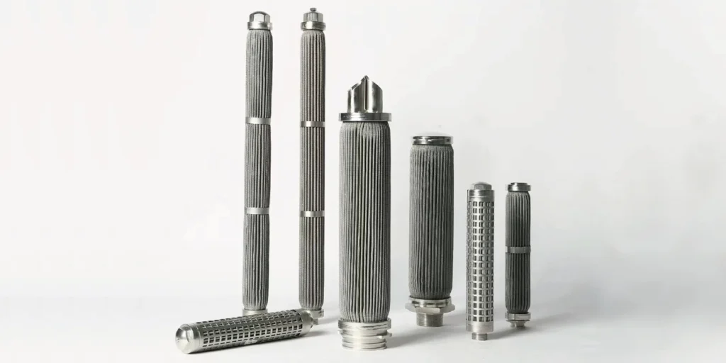
Two pleated cartridges may have the same length, diameter and micron label but show different pressure drops after installation. Their media, pleat channels, support layers and available filtration area may differ, as may the flow and fluid temperature used for the comparison. This guide explains pleated filter cartridge pressure drop for industrial buyers and shows how to investigate a difference without confusing low resistance with proven filtration performance.
What Determines Pleated Filter Cartridge Pressure Drop?
Pressure drop is the pressure difference between two defined points as fluid flows through the filter assembly. For a pleated cartridge, it depends on the medium, the area actually accessible to flow, the pleat channels, supports, core and end connections. Flow, viscosity and accumulated contaminants also change the reading.
Compare readings only after defining the measurement locations and operating conditions. A housing inlet-to-outlet reading can include losses from the housing and connections in addition to the cartridge. It is not automatically identical to a laboratory measurement across the element alone.
Separate Clean Pressure Drop From Loaded Pressure Drop
Clean pressure drop is the resistance observed for a clean element under specified test conditions. Once particles accumulate, the medium and pleat channels may offer more resistance. The rate of change depends on the contaminant, its concentration, how it deposits and the distribution of flow through the cartridge.
Do not compare one supplier's clean-water curve with another supplier's reading for cold oil or a partially loaded element. Record the fluid, temperature, flow, flow direction, pressure-tap locations and clean or loaded condition. For gas, specify whether flow is given at operating conditions or at a stated reference condition.
The industrial cartridge sizing guide explains how flow and area enter the selection process. The relevant comparison is the complete assembly at comparable conditions, not an isolated micron label.
Pleat Count and Accessible Area
Pleating folds more medium into the available envelope. When that area remains accessible, flow is distributed over more surface and average flow per unit area is lower. However, the unfolded sheet area, exposed area after assembly and area effectively used during service need not be identical.
More folds can narrow the channels between adjacent pleats. Depending on the design and contaminant, fluid distribution may become less uniform or deposits may bridge a channel. A higher pleat count therefore does not guarantee a lower pressure drop or longer service life. Pleat height, spacing, media thickness, support and contaminant behavior must be reviewed together.
Porvair's metal-fiber description describes pleating as a way to increase available filtration area for its medium. That does not establish a universal area or pressure-drop multiplier for another manufacturer's element.

Media and Supports Matter
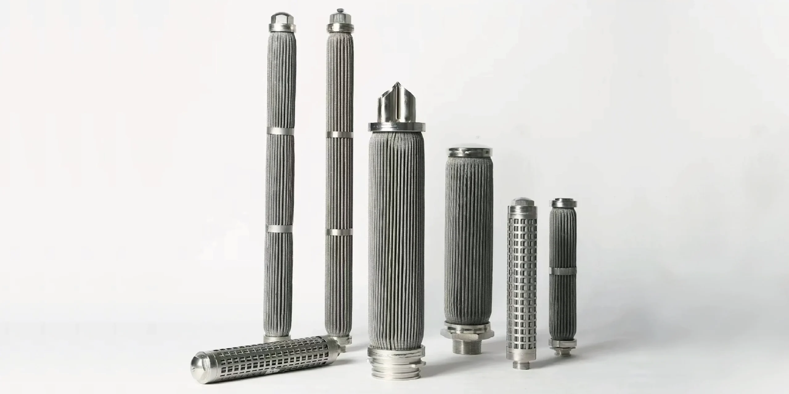
Woven mesh, sintered mesh and sintered metal fiber felt can be formed into pleated cartridges, but their structures differ. Permeability, thickness, layer construction and particle-retention behavior affect resistance and loading. A visible protective layer may not be the layer that determines particle retention.
Support mesh, drainage layers, a perforated core, guards, end fittings and housing connections also form part of the flow path. Restriction in any of these areas can contribute to the measured difference. A cartridge with more media area can still have substantial losses elsewhere in the assembly.
Pall's filter-media overview distinguishes woven wire media from depth-type metal fiber media. Its proprietary product figures are not SINFT ratings. Ask for the appropriate pressure-drop and filtration evidence for the actual pleated filter cartridge being considered.
How Flow and Viscosity Change the Reading
Increasing flow generally increases resistance, but the relationship for the whole assembly is not necessarily linear across every operating range. In an appropriate laminar regime, the media contribution can often be approximated as proportional to viscosity and flow, provided the geometry and other conditions remain comparable. Housing and local losses may behave differently.
For a hydraulic application, cold startup can produce a higher initial differential pressure because the oil is more viscous. Compare the same temperature and flow before attributing the increase to contamination. The viscosity and pressure-drop guide explains this effect in more detail.
Never extrapolate a clean-water curve to a viscous fluid or a different temperature without confirming the assumptions and limitations with the supplier. For non-Newtonian fluids, compressible gases or changing phase conditions, a simple viscosity correction may be unsuitable.
A Practical Comparison Checklist
| Check | What to establish before comparing |
|---|---|
| Measurement boundary | Element-only or housing inlet-to-outlet; pressure-tap locations and instrument condition. |
| Fluid and temperature | Fluid identity, temperature and relevant viscosity at the comparison point. |
| Flow | Actual operating flow and, for gases, the reference basis. |
| Element condition | New, cleaned or loaded; time and contaminant exposure. |
| Medium and support | Media construction, layers, core, guard and flow direction. |
| Area and pleats | How the area is defined, channel geometry and possible obstruction. |
| Filtration performance | Rating definition, test method and required removal performance. |
An unusually low reading does not independently prove better performance. A bypass path, damaged medium, instrument problem or different flow can also change the reading. Check seating, sealing and integrity alongside the operating measurements.
Why Pressure Drop Rises in Service
Particles may build a surface layer, accumulate within a depth medium or obstruct the entrances to pleat channels. Sticky or deformable material can behave differently from hard, discrete particles. The same nominal rating does not guarantee the same loading pattern or time to the agreed changeout point.
Before diagnosing blockage, check whether flow increased, temperature fell or a valve and downstream restriction changed. Confirm pressure taps and the instrument, then compare the reading with a baseline established at similar conditions. A differential-pressure trend is useful evidence, but it does not identify the cause by itself.
| Observation | First review |
|---|---|
| High reading immediately after installation | Flow, viscosity, measurement locations, cartridge configuration and installation. |
| High only during cold startup | Temperature and viscosity, flow and the approved operating limits. |
| Gradual rise under comparable conditions | Contaminant loading, upstream process changes and agreed maintenance criteria. |
| Sudden unexpected decrease | Flow and instrumentation, seal seating and possible damage or bypass. |
| High after cleaning | Comparable test conditions, residual deposits and integrity of the assembly. |
Use the equipment manufacturer's approved limits and maintenance procedures. Do not infer an allowable operating differential pressure or backwash capability from the clean pressure-drop curve. The flow-direction guide explains why support and reverse loading are separate concerns.
Cleaning and Replacement Decisions
A compatible cleaning method may restore resistance, but a lower pressure drop after cleaning does not prove that the element remains intact. Damage or bypass can also lower resistance. Review the media, joints and seals and apply the agreed acceptance checks at comparable conditions.
For a replacement, physical fit matters as well as hydraulic and filtration performance. The pleated cartridge dimensions guide covers interfaces and housing fit, while the working-principle guide explains how the medium and support form the flow path.
What Buyers Should Send With an RFQ
Provide the working fluid and temperature range, normal and maximum flow, viscosity where available, flow direction, contaminant description, required filtration performance and acceptable clean pressure drop. Include the pressure measurement boundary and any terminal differential-pressure requirement.
Also provide the housing drawing, end connection, seals, required materials and cleaning or reverse-flow duty. If replacing an existing element, share its part number, dimensions and baseline readings with their conditions. Unknown test conditions should be marked as unknown instead of assumed.
SINFT supplies pleated metal elements in different media and end configurations. Use the custom filter manufacturer page and the contact inquiry form to discuss the complete assembly and confirm what data and inspection records can be provided for the order.
Frequently Asked Questions
Do more pleats always reduce pressure drop?
No. More pleats can increase geometric media area, but channel spacing and flow distribution also matter. Crowded channels or deposits can reduce access to part of that area. Compare the complete element and its measured clean pressure drop under the same conditions. Pleat count alone does not establish filtration efficiency, usable area or service life.
Does a lower micron rating always mean a higher pressure drop?
Not necessarily. Rating definitions, media structure, thickness and accessible area differ between designs. A comparison needs both a defined removal requirement and pressure-drop data at the same fluid and flow conditions. Do not assume that two ratings use the same test method or that micron size alone predicts the resistance of the complete assembly.
Can a clean-water curve predict cold-oil pressure drop?
It can provide a reference only when the supplier's assumptions are applicable. Oil viscosity changes with temperature, and housing or local losses may not follow the same simple scaling as the medium. Give the supplier the actual fluid, temperature and flow. Confirm how the comparison was calculated and do not treat an extrapolation as a measured result.
Why does pressure drop rise after installation?
Accumulated particles may increase resistance at the medium or in pleat channels. However, higher flow, colder fluid, a changed valve position or an instrument issue can also alter the reading. Compare against a baseline under similar conditions and inspect according to the equipment procedure. A rising number alone does not identify the cause or prove that the cartridge is defective.
Can low differential pressure indicate a problem?
Yes. It may indicate a suitable clean assembly, but an unexpected fall can also result from a lower flow, a measurement issue, damage or a bypass path. Compare operating conditions and review the seals, seating and integrity. Pressure drop alone cannot prove that the required particle-removal performance is being achieved.
Is housing pressure drop the same as element pressure drop?
Not always. A housing inlet-to-outlet measurement may include losses from the inlet, outlet, internal passages and connections. A cartridge-only test can have different pressure-tap locations and fixtures. Before comparing values, identify both measurement points and the test setup. Ask for a consistent basis rather than attributing the entire housing reading to the medium.
Can every pleated metal cartridge be backwashed?
No. Reverse flow loads the medium and support differently from normal filtration. The construction, seals, joints and operating conditions must be suitable for the approved cleaning method. Confirm the allowable reverse duty for the actual assembly. A metal material or a low clean pressure drop does not establish universal backwash capability or a fixed number of cleaning cycles.
What information helps compare replacement cartridges?
Provide fluid, temperature, viscosity, flow, flow direction and contaminant information, plus the required filtration performance and pressure-drop measurement boundary. Include the housing drawing, end connections, seal and cleaning requirements. Ask for comparable clean pressure-drop evidence and the applicable structural limits. A matching length and micron label are useful identifiers but do not establish equivalent operating behavior.
Final Thoughts
Pleated cartridge pressure drop reflects the complete flow path, fluid conditions and the state of the medium. Compare clean and loaded readings on a consistent basis, and examine accessible area and support as well as the micron label. Send SINFT your operating data and housing details so a replacement can be reviewed for fit, filtration performance and pressure-drop requirements together.