Two pleated cartridges can fit the same housing and carry the same micron label, yet behave differently once flow starts. One may develop more pressure drop, load unevenly or allow fluid to bypass a damaged seal. This guide explains the pleated filter cartridge working principle for industrial metal elements, showing how the flow path, filter medium and complete assembly determine performance beyond the number of visible folds.
Pleated Filter Cartridge Working Principle: The Direct Answer
A pleated filter cartridge works by forcing fluid through a porous medium folded into a compact cylindrical pack. The medium retains particles according to its structure and verified filtration performance. The pleats accommodate more media within the cartridge envelope, while supports, end joints and seals maintain the intended flow path.
In a representative outside-to-inside arrangement, feed surrounds the element, crosses the pleated wall and enters the central passage before leaving through the outlet. The flow direction depends on the design. A different housing or cartridge can use inside-to-outside flow, so the drawing and installation information must establish the actual route.
The practical distinction is straightforward: the pleats provide area; the filter medium performs particle separation; the assembly keeps fluid on the correct path. All three must work together.
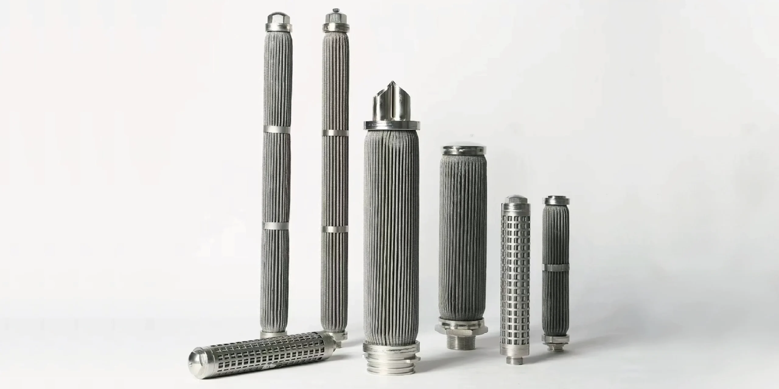
Follow the Fluid Through the Complete Assembly
The housing first directs feed toward the intended upstream side of the cartridge. In the outside-to-inside example, fluid moves through the spaces between the pleats and crosses the porous wall. Retained material accumulates at or within the filtering medium, depending on its construction and the contaminant.
After crossing the medium, filtrate passes through the downstream support structure and into the inner passage. It then leaves through the outlet connection. The core provides support and a flow path; it is not automatically the fine filtering layer simply because it has visible holes.
End caps, welded transitions and the housing interface close unwanted routes around the media. A leaking end joint or incorrect seal can create a parallel path that lets some fluid avoid the filtration layer. Good media cannot compensate for that bypass.
Confirm direction before interpreting loading or pressure capability. The support arrangement that resists inward loading may not provide equivalent resistance in reverse. Our filter element flow-direction guide explains why filtration direction, support and backwashing must be considered together.

What Each Part Actually Does
The cartridge is an assembly with distinct filtration, hydraulic, mechanical and sealing functions. Some designs combine functions in one layer, while others use separate components. Do not assume that every element has the same layer count or construction.
| Part | Function | Performance implication |
|---|---|---|
| Filtering medium | Provides the porous structure where particles are retained. | Controls separation behavior and contributes flow resistance. |
| Pleated geometry | Accommodates media area inside a defined envelope. | Changes local flow, access to the medium and space for deposits. |
| Support or drainage layers | Support the medium and provide flow paths where included. | Affect resistance, stability and usable area. |
| Perforated core or outer guard | Provides design-specific support or protection. | Must suit the intended pressure-loading direction and flow. |
| Seam and end-cap joints | Complete the media pack and connect it to the ends. | A defect can create bypass or compromise structural integrity. |
| End connection and seal | Locate the cartridge and separate housing flow regions. | Fit and sealing determine whether fluid actually crosses the medium. |
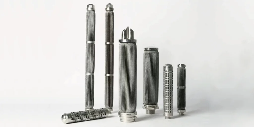
For SINFT pleated filter cartridges, the medium can be woven wire mesh, sintered wire mesh or sintered metal fiber felt. These choices can be folded into a similar overall shape while producing different particle-capture and loading behavior.
Pleated Shape Does Not Mean One Filtration Mechanism
Pleating describes geometry. It does not tell you whether the element primarily captures particles on a surface or within a porous structure.
With woven mesh, defined openings can provide a strong surface-screening function. Particles that cannot pass the relevant openings are retained, although particle shape, deformability and operating conditions affect real behavior. A multilayer sintered mesh assembly also includes supporting structures; the visible outer opening may not be the opening that controls filtration.
Sintered metal fiber felt contains a network of bonded fibers. Depending on its grade and structure, particles can be retained within the porous thickness as well as at the surface. A pleated fiber medium therefore should not be described as a simple screen merely because it has folds.
Pall's polymer filter-media overview distinguishes woven wire surface media from depth-type metal-fiber media. That distinction helps explain why media selection changes capture behavior; the proprietary grades and performance figures on that page are not ratings for SINFT products.
For the material structure itself, see sintered metal fiber felt filters. Neither surface nor depth capture is universally better. The relevant question is how the medium handles the actual particles, required removal performance and regeneration duty.
Why Pleats Can Improve Performance
Pleats allow a longer sheet of medium to occupy a limited cartridge envelope. If the additional area remains accessible to flow, the same total flow can be distributed over more filtering surface. This lowers average media flux, meaning flow per unit of active area.
A useful relationship is:
Average media flux = volumetric flow ÷ active filtering area
As a hypothetical liquid-flow example, 60 L/min through 0.20 m² corresponds to an average flux of 300 L/min/m². The same flow through 0.10 m² corresponds to 600 L/min/m². These are arithmetic examples, not SINFT product ratings, recommended operating points or predictions of service life.
More accessible area can reduce the media contribution to clean pressure drop under comparable conditions and distribute retained material over a larger surface. However, the complete cartridge and housing still introduce resistance. Extra media area does not guarantee a proportional increase in flow capacity or time between cleaning.
Porvair's sintered metal-fiber description identifies pleating as a way to increase available filtration area. The benefit depends on the medium and finished design; it does not establish a universal multiplier for all pleated cartridges.
Why More Pleats Do Not Always Mean Better Filtration
Pleat count must be considered with pleat height, spacing, media thickness, supports and the available flow channels. Adding folds within the same envelope can narrow the passages between them. If fluid or deposits cannot use those passages effectively, geometric area overstates the area contributing usefully in service.
Closely packed folds can also make loading and cleaning less uniform. Sticky material may bridge between surfaces, while deposits near channel entrances can reduce access to deeper areas. These effects depend on the contaminant and operating conditions; a higher pleat count is not automatically a defect, but it needs a design basis.
Distinguish the unfolded area of the medium from the area exposed after assembly and from the area usefully participating under a particular flow and loading condition. Ask what an area figure includes. End joints, blocked regions and contact between components can affect the interpretation.
For gas service, also establish how volumetric flow is referenced. A normal or standard gas-flow figure cannot be inserted into an operating-volume flux comparison without the necessary conversion. The general area principle remains useful, but the quantities being compared must describe the same conditions.
Pressure Drop Reflects More Than the Micron Label
Pressure drop is the pressure difference associated with fluid moving through the installed flow path. Across a cartridge, it depends on the medium, usable area, support layers, core, connections and loading condition. A housing measurement can include additional losses outside the cartridge, depending on tap locations.
For clean media in a suitable laminar-flow regime, increasing viscosity or flow generally increases the media pressure drop when the other conditions remain comparable. That relationship is a useful principle, not a guarantee that the entire assembly follows a single linear equation at every operating point.
As particles accumulate, resistance commonly increases. But a pressure-drop rise does not, by itself, identify the cause. Colder fluid, increased flow or a restriction elsewhere can change the reading. Compare operating conditions before attributing every increase to filter loading.
The industrial filter cartridge sizing guide develops flow and area checks further. Here, the working-principle lesson is to connect the reading to the actual medium, construction and operating state rather than treating pressure drop as a direct measure of filtration efficiency.
What Really Affects Performance in Service?
Evaluate particle-removal performance, resistance, loading behavior and mechanical integrity separately. A single attractive number rarely represents all four.
| Driver | What changes in the cartridge | What the buyer should establish |
|---|---|---|
| Medium and rating basis | Particle capture, permeability and loading location. | Relevant removal requirement and its verification method. |
| Accessible media area | Average media flux and distribution of retained material. | How the stated area is defined and supported by the design. |
| Fluid and operating flow | Resistance and distribution through the assembly. | Flow range, viscosity and temperature at the operating condition. |
| Contaminant behavior | Surface cake, depth loading or channel bridging. | Particle distribution, concentration and sticky or deformable content. |
| Support and loading direction | Resistance to deformation and changes in flow channels. | Intended forward and reverse differential-pressure duties. |
| Sealing and joints | Whether fluid crosses the intended filtration layer. | Correct interface, sealing condition and assembly integrity. |
A low pressure drop can be desirable, but it is not proof of good particle removal. It could also occur with a more open medium, an incorrectly fitted cartridge or a bypass path. Likewise, a low micron number does not establish removal efficiency without a rating convention and relevant evidence.
How the Principle Applies to Industrial Duties
For a hydraulic application, compare performance at the relevant fluid temperature and flow range. Cold, viscous oil can produce a different initial pressure drop from warm oil. A cartridge that looks lightly loaded may still experience a demanding differential-pressure condition.
In a stream containing sticky particles or gels, added geometric area may be less useful if deposits block the pleat channels early. The medium and channel geometry need to be reviewed together. A clean-water curve alone cannot establish the loading behavior of a very different process stream.
For hot liquids or gas duties, the assembly must remain compatible with temperature, chemistry and mechanical loading. The capability of stainless steel media alone does not establish the capability of seals, welded joints or the complete cartridge. Gas-flow comparisons also require consistent pressure, temperature and volume-reference information.
For high bulk-solids loads, consider whether upstream separation is needed. A fine pleated element may be the appropriate polishing stage without being the appropriate first collection point for every large piece of debris.
Cleaning and Reuse Must Preserve the Flow Path
Metal construction can allow regeneration when the complete element and contaminant suit an approved cleaning method. Reuse depends on restoring acceptable performance while preserving the media, joints, supports and seals.
A lower pressure drop after cleaning is useful evidence of reduced resistance under comparable conditions. It does not independently prove intact filtration performance. A damaged medium or bypass defect can also reduce resistance, so the acceptance decision may require integrity and condition checks in addition to a flow comparison.
Backwashing reverses the pressure-loading direction. It should only be used within the confirmed capability of the assembly. Reverse-flow capability, cleaning chemistry, ultrasonic treatment and repeated regeneration cannot be inferred from the pleated shape or the metal grade alone. Cleaning parameters and release criteria need to be agreed for the actual design.
Turn the Explanation into a Better Product Discussion
Ask a supplier to identify the complete flow path and the function of each layer. Then establish what supports the claimed filtration performance, area and pressure-drop behavior. This is more informative than comparing a photograph, nominal length and pleat count.
For an RFQ or replacement review, provide:
- Fluid, operating temperature, viscosity where relevant and chemical composition.
- Minimum, normal and maximum flow, with gas reference conditions if applicable.
- Contaminant characteristics and required particle-removal performance.
- Clean and terminal differential-pressure requirements and intended flow direction.
- Housing interface, seals, available envelope and drawing or old sample.
- Cleaning method, reverse-flow duty and required inspection records.
SINFT supplies pleated metal cartridges using woven mesh, sintered mesh and sintered fiber felt, with standard or custom end arrangements based on the confirmed duty. The appropriate construction and allowable conditions require review of the complete assembly. No single pleat count, area figure or material label establishes a universal operating rating.
Use the pleated cartridge selection guide for the detailed purchasing sequence. For drawing-based manufacture or replacement matching, review the custom filter manufacturer page and send your operating data through the contact inquiry form.
Frequently Asked Questions
Does a pleated cartridge always use outside-to-inside flow?
No. Outside-to-inside flow is one arrangement, while other cartridges or housings use inside-to-outside flow. Confirm the actual design from the drawing and installation information. Direction affects which surfaces collect contaminants, which supports resist pressure loading and how cleaning is performed. Do not reverse a cartridge or apply backwashing simply because its cylindrical shape appears symmetrical or the connections physically fit.
Do the pleats determine the micron rating?
No. Pleats describe the folded geometry, while the medium and its verified performance determine the particle-removal claim. The rating also needs a definition and relevant test basis. Adding folds does not automatically make the pores finer or turn a nominal label into an absolute rating. Compare removal performance separately from the amount of medium accommodated inside the cartridge envelope.
Is every pleated metal cartridge a surface filter?
No. A pleated cartridge can use a medium with predominantly surface capture or a porous structure that also captures particles within its thickness. Woven mesh and sintered metal fiber felt do not behave identically merely because both can be pleated. Establish the medium, its structure and its response to the actual contaminant before assuming a loading pattern or cleaning method.
Why can two equally sized cartridges have different pressure drops?
Their media permeability, thickness, accessible area, supports, cores and connections may differ. The fluid, flow rate, temperature and loading condition also affect the comparison. Equal length and diameter establish only part of the geometry. Compare relevant pressure-drop information under consistent conditions and confirm whether the reading covers the cartridge alone or includes housing losses before deciding that two elements are equivalent.
Does twice the media area mean twice the service life?
Not automatically. More accessible area can lower average media flux and spread deposits, but loading depends on the contaminant, channel geometry, flow distribution and terminal acceptance criterion. Some area may become poorly used as deposits develop. Treat area as a useful design input and compare performance under representative conditions rather than applying a universal service-life multiplier to the unfolded sheet area.
Can a low pressure drop indicate a problem?
Yes. Low resistance can reflect a suitable clean design, but an unexpected reduction may also warrant checking the medium, installation and bypass paths. Interpret the reading alongside flow, viscosity, temperature and the prior operating state. Pressure drop alone cannot establish particle-removal efficiency or integrity. A cartridge should satisfy the required filtration performance as well as the acceptable resistance to flow.
Can every stainless steel pleated filter be backwashed?
No. Backwashing applies reverse differential pressure and requires a suitable support arrangement, joints, media and operating procedure. A cartridge designed for forward filtration may have a different reverse capability. Confirm the permitted method and conditions with the supplier for the complete assembly. Stainless steel construction or a reusable product description does not independently establish unlimited reverse flow or repeated cleaning capability.
What is the most useful information for a replacement inquiry?
Provide a drawing or sample with the housing interface, medium if known, removal requirement, fluid, flow range, temperature and differential-pressure duty. Include flow direction, seals and cleaning conditions. These details help distinguish a physically similar element from a functionally suitable replacement. If a parameter is unknown, identify the gap so it can be reviewed instead of silently treating the old part's appearance as proof.
Final Thoughts
A pleated cartridge performs well when its medium, accessible area, supports and seals work as one assembly under the actual duty. Understand where fluid travels, where particles are retained and what the pressure-drop reading includes before comparing designs. Send SINFT the operating conditions and housing information so the discussion can move from visible pleat count to a construction suited to your filtration requirement.